Arduino IoT Cloud Home Automation Project using ESP32
Last Updated on August 24, 2024 by Engr. Shahzada Fahad
Table of Contents
Arduino IoT Cloud Home Automation, Description:
Arduino IoT Cloud Home Automation Project using ESP32- Building a Home Automation system with Arduino IoT Cloud is far easier than building it with the Blynk IoT platform. A dashboard on your cell phone is automatically generated which you can use to control things from remote locations if you have access to the internet. The Arduino IoT Cloud Remote App can be installed on both IoS and Android cell phones. You can also control your electrical devices through a dashboard from your computer screen, now the computer dashboard can be quite handy in situations when you have to monitor and control multiple things.
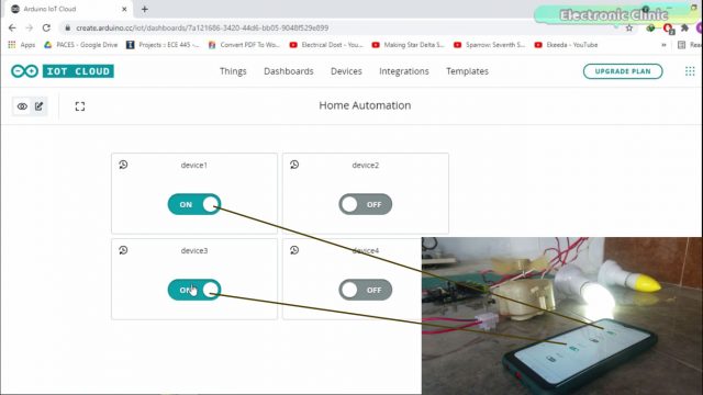
As you can see when I turn ON a button on my computer dashboard, the same button is also turned ON, on the cell phone dashboard. The computer dashboard and cell phone App are working together and make a dual control system which means any electrical device that is turned ON or turned OFF using the computer dashboard can also be turned OFF or turned ON using the cell phone. In this article, you will learn how to make Home Automation system using Arduino IoT cloud and ESP32 WiFi + Bluetooth module.
Altium Designer:

Altium Designer is the world’s most trusted PCB design system. Altium Designer enables engineers to effortlessly connect with every facet of the electronics design process. Over 35 years of innovation and development focused on a truly unified design environment makes it the most widely used PCB design solution. With Altium Designer you can create PCB designs with an intuitive and powerful interface that connects you to every aspect of the electronics design process. Route it your way through any angle, tune for delay, Push, Slide, and Walkaround faster than ever. Interact and collaborate with mechanical designers like never before in a photo-realistic, 3D design environment. If you want to get started with the Altium designer, you can click on the get started.
In my previous article, I explained how to get started with the Arduino IoT Cloud and explained the maximum basic things including how to register an account, how to install the ArduinoCreateAgent, how to make a dashboard, and how to write a basic program for monitoring a sensor and for controlling an LED. So, I highly recommend reading my previous getting started tutorial on the Arduino IoT Cloud. Without any further delay, let’s get started!!!
Amazon Purchase Links:
ESP32 WiFi + Bluetooth Module(Recommended)
*Disclosure: These are affiliate links. As an Amazon Associate I earn from qualifying purchases.
ESP32 Home Automation Circuit Diagram:
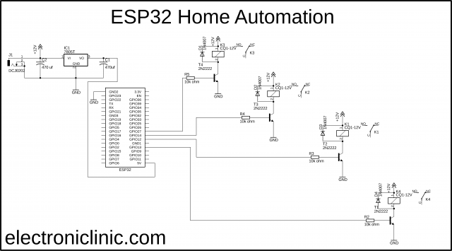
J1 is the female power jack and this is where we connect a 12v adaptor, battery, or solar panel. Two 470uf decoupling capacitors are connected at the input and output sides of the 7805 voltage regulator. The output of the voltage regulator is connected with the 5v pin of the ESP32 module and the ground of the power supply is connected with the ground of the ESP32 module.
These are 12v SPDT type relays and cannot be directly controlled using the ESP32 Module, So, that’s why we need a driver to control these relays. You can use a relay driver IC or you can use a 2n2222 NPN transistor and a 10k resistor. One pin of the relay coil is connected with the collector of the 2n2222 NPN transistor while the other pin of the relay coil is connected with the 12 volts. The emitter of the transistor is connected with the ground while the base is connected with the 10k ohm resistor.
Now to control these relays you simply need to connect these 10k resistors with the ESP32 I/O pins. In this project, I am using the GPIO pins 13, 12, 14, and 27. I will be using the same pins in the programming.
These 4 relays can be used to control 4 different types of loads. The loads should be connected with the common and normally open legs of the relays. For the making watch my video tutorial on the ESP32 & Blynk application based Home Automation Project.
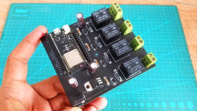
Here is my ESP32 Development board which can be used for monitoring different sensors and controlling different DC and AC loads. If you want to make the same development board then you can download the Gerber files. Now, let’s start with the Arduino IoT Cloud. As I have already explained all the steps in my previous getting started tutorial, so there is nothing left to talk about, but still, if you find anything difficult to understand then you can read my article available on www.electroniclinic.com I will provide a link in the description.
Arduino IoT Cloud Home Automation:
To get started with the Arduino IoT Cloud, first, you will need to create an account, which I have already explained in my getting started tutorial on the Arduino IoT Cloud.
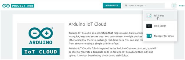
If you have already an account click on the IOT Cloud.
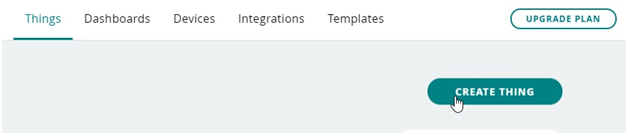
Now, click on the CREATE THING in which we will create the variables for the various devices.
Creating variables:
Now we will create variables in our case we are using four variables through which we will control four appliances. So, to add the variables click on the add variable, we will go to the setup in which we will click on the ADD VARIABLE.

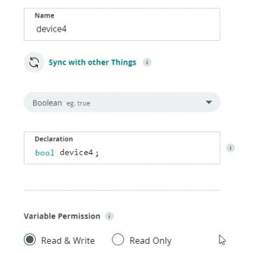
Now, first of all, we will create a variable for the first appliance with the name of device1 then in the select variable type, we will select the Alexa compatible in which we will select the switch.

Then we will click on the add variable.

In a similar way, we will add a second variable and give it a name device2

Then we will add a third variable for the third appliance.

Finally, we will add a fourth variable for the fourth appliance.
Now, all the variables have been added and now we will configure the device

Configuring the device:
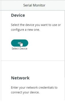
Now to add the device click on the add device.
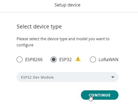
Now we will select the device which we will want to add we will select the third party device
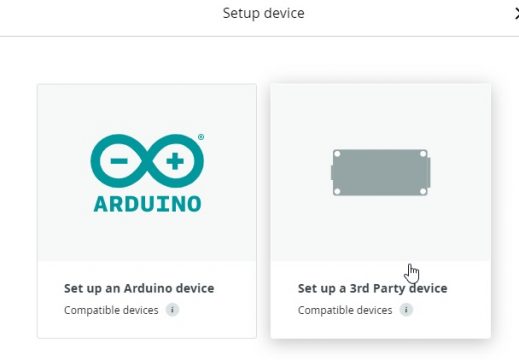
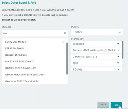
After that, we will select the ESP32 device and select the ESP32 dev module and click on the continue button.
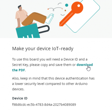
Now give a name to the device which is ESP32 and click on the Next button.

Then we will click on the download button in order to use the security key and device id.
Then click on the, I saved my device and secret key and click on the continue button.
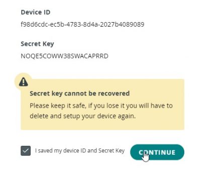
After clicking on the continue button the ESP32 module will be successfully added and click on the done button.

Configuring the network:
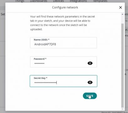
Now after that, we will configure the network in order to connect to the wifi, we will click on the network button.
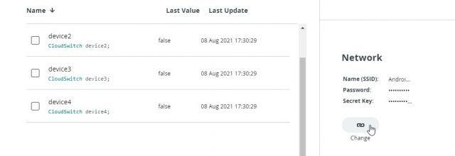
When we will click on the network we will add the name of the wifi router and password. Then copy the secret key from the downloaded pdf and paste it in the secret key box and click on the save.
Arduino IoT Cloud Dashboard, Creating buttons:
After that click on the dashboards in order to design the various button for controlling the appliances.

Now click on the edit button and give the name to the project which is home automation.

Then click on the add button in which we will click on the switch.

Now give a name to the switch as device 1 and click on the link button

When we will click on the link button we will select the variable and click on the link button and the button will be linked to the variable.

In a similar way, we will add the buttons for the other three appliances and link the variable for each appliance.

After that, we will click on the thing and go back to the menu in order to write the code for each appliance. Now click on the sketch button in order to write the code

Now click on the open full editor button to write the code

Arduino IoT Complete code:
|
1 2 3 4 5 6 7 8 9 10 11 12 13 14 15 16 17 18 19 20 21 22 23 24 25 26 27 28 29 30 31 32 33 34 35 36 37 38 39 40 41 42 43 44 45 46 47 48 49 50 51 52 53 54 55 56 57 58 59 60 61 62 63 64 65 66 67 68 69 70 71 72 73 74 75 76 77 78 79 80 81 82 83 84 85 86 87 88 89 90 91 92 93 94 95 96 97 98 99 100 101 102 103 104 105 106 107 108 109 110 111 112 113 114 115 116 117 118 119 120 121 122 123 124 125 |
<span style="font-size: 14pt; font-family: 'times new roman', times, serif;">/* Sketch generated by the Arduino IoT Cloud Thing "Untitled" https://create.arduino.cc/cloud/things/2ea51cca-f439-44a8-820d-1019d9c932cf Arduino IoT Cloud Variables description The following variables are automatically generated and updated when changes are made to the Thing CloudSwitch device1; CloudSwitch device3; CloudSwitch device2; CloudSwitch device4; Variables which are marked as READ/WRITE in the Cloud Thing will also have functions which are called when their values are changed from the Dashboard. These functions are generated with the Thing and added at the end of this sketch. */ #include "thingProperties.h" int device_1 = 13; // gpio 13 int device_2 = 12; // gpio 12 int device_3 = 14; // gpio 14 int device_4 = 27; // gpio 27 int LED = 2; void setup() { // Initialize serial and wait for port to open: Serial.begin(9600); // This delay gives the chance to wait for a Serial Monitor without blocking if none is found delay(1500); pinMode(device_1, OUTPUT); pinMode(device_2, OUTPUT); pinMode(device_3, OUTPUT); pinMode(device_4, OUTPUT); pinMode (LED, OUTPUT); // Defined in thingProperties.h initProperties(); // Connect to Arduino IoT Cloud ArduinoCloud.begin(ArduinoIoTPreferredConnection); /* The following function allows you to obtain more information related to the state of network and IoT Cloud connection and errors the higher number the more granular information you’ll get. The default is 0 (only errors). Maximum is 4 */ setDebugMessageLevel(2); ArduinoCloud.printDebugInfo(); } void loop() { ArduinoCloud.update(); // Your code here } void onDevice1Change() { // Do something if(device1==1) { digitalWrite(LED, LOW); digitalWrite(device_1, LOW); } else { digitalWrite(LED, HIGH); digitalWrite(device_1, HIGH); } } void onDevice3Change() { // Do something if(device3==1) { digitalWrite(LED, LOW); digitalWrite(device_3, LOW); } else { digitalWrite(LED, HIGH); digitalWrite(device_3, HIGH); } } void onDevice2Change() { // Do something if(device1==1) { digitalWrite(LED, LOW); digitalWrite(device_2, LOW); } else { digitalWrite(LED, HIGH); digitalWrite(device_2, HIGH); } } void onDevice4Change() { // Do something if(device4==1) { digitalWrite(LED, LOW); digitalWrite(device_4, LOW); } else { digitalWrite(LED, HIGH); digitalWrite(device_4, HIGH); } } </span> |
Uploading the code:
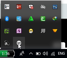
After writing the code we will get a message to install Arduino agent in order to upload the code to the ESP32 so we will click on the learn more and download the agent and install it in the computer.

This option shows that the agent is running on the computer
Then we will select the board and click on the ok button.
Now the board is successfully added and we will click on the upload button
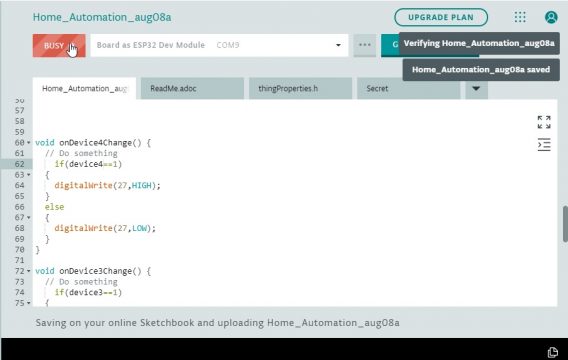
After uploading the code to the esp32 we will be able to control the appliances from the mobile dashboard and also from the Laptop dashboard.
Video Tutorial:
Discover more from Electronic Clinic
Subscribe to get the latest posts sent to your email.


