Make your own SMS GPS Security Tracking System with Google’s Map URL Link
Last Updated on August 17, 2024 by Engr. Shahzada Fahad
Table of Contents
SMS GPS Security Tracking System:
SMS GPS Security Tracking System– If you feel like you are being followed by someone or if you are stuck in the middle of nowhere and you need immediate help. You might be thinking why not call and tell me location? Well, it’s difficult to talk to someone in a situation like this, and as you are driving your location updates every second. So the best solution is to automatically send your location after every 2 minutes. This way your friend or family member can easily find your location using Google’s map. The Arduino will take care of everything, while you can focus on driving.
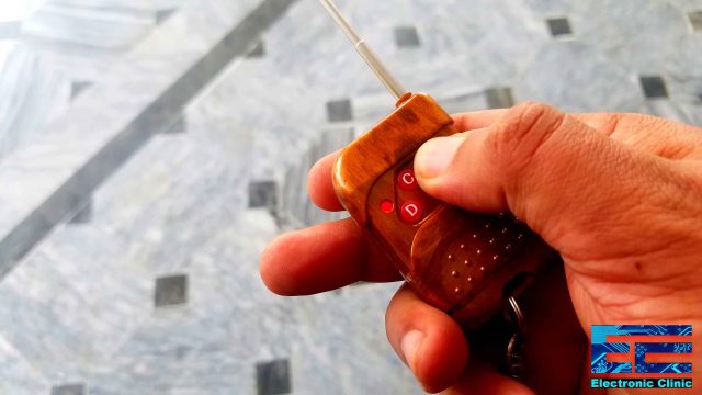
Simply take out this wireless keychain press button A to activate the timer and the Arduino will start sending your current GPS location in a text message along with Google’s map URL link after every two minutes, the time duration can be changed as per your requirement.
You can activate the normal mode by simply pressing the button B and the Arduino will stop sending the messages. Besides this, I also added the anti-theft feature which I will discuss in a few seconds, but first a few words about the sponsor of this project.
About the Sponsor of this project, PCBWay:
![]()
High quality & Only 24 Hours Build time
The PCB board used in this project is sponsored by the PCBWay Company. PCBWay is quite professional in the field of PCB manufacturing; you can try their services at extremely low prices, Only 5 dollars for 10 PCBs and 30 dollars in total for 20 PCBs assembly, besides this the new members also get a 5 Dollars bonus.
I also added the Anti-theft feature which can be activated by pressing the button C on the YK04 Transmitter.

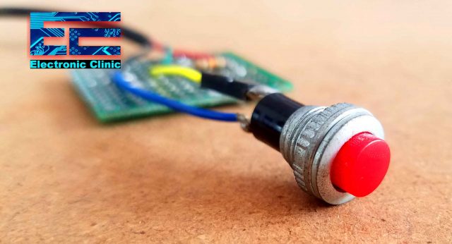
For the demonstration purposes, I am using a push-button which of course you can replace with any other sensor, which can be fixed in a motor cycle or Car for detecting any activity.
Anyhow, when this pushbutton is pressed, a timer is activated and the Arduino will start sending the messages which consist of the longitude and latitude values along with Google’s map URL link. You can simply deactivate the anti-theft mode by pressing button D on the keychain. Now if the button is pressed the Arduino won’t send any messages.
So, if you feel any danger, or stuck somewhere then you can activate the automatic message-sending mode, the rest Arduino will take care of. It will keep sending messages to your family member or a friend depending on the cell phone number. You can modify the program to send a single message on multiple numbers. I have already explained this in my previous tutorial based on “How to send security alert messages to multiple numbers”.
The anti-theft mode should be activated after you have parked your bike or car. I already demonstrated this and now you have the idea of how it works. My recommendation is to use a vibration sensor instead of using a pushbutton.
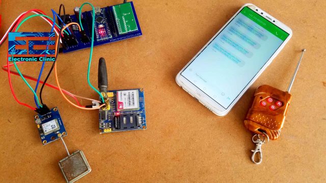
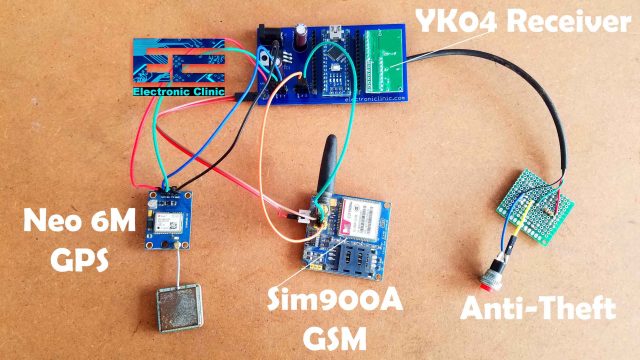
The heart of this project is the Arduino Nano to which the YK04 receiver, Neo 6M GPS, and GSM SIM900A modules are connected.
In this Project, we will cover,
- Components Details
- Complete Circuit Diagram
- Soldering
- Programming and finally
- Testing
Without any further delay, let’s get started!!!
Note: for the live tracking based on the IoT read my article”Nodemcu GPS Tracker using Arduino Nodemcu esp8266 and Blynk“.
Amazon Purchase Links:
Arduino Nano USB-C Type (Recommended)
YK04 5V 4 channel Remote Control Switch
*Disclosure: These are affiliate links. As an Amazon Associate I earn from qualifying purchases.
4-Channel YK04 Wireless Transmitter and Receiver:
![]()
This is the YK04 280-433Mhz, 4 channel Receiver module with a 4 channel Transmitter provided with the buttons A, B, C, and D. 4 data outputs D0 to D3 are for 4 buttons remote control which is a small size and easy to carry. The Data pin will output a high level when the corresponding button is pressed. The working voltage of this module is 5volts.
The YK04 Wireless Receiver module can be easily interfaced with all types of 5V supported controller boards. You can safely use this module with the Arduino Uno, Arduino Nano, Arduino Mega, etc. The connection of the YK04 receiver module with the Arduino Nano will be explained in the circuit diagram in a minute.
Neo 6m GPS Module Pinout:
![]()
This is the Neo 6M GPS module used in the SMS GPS Security Tracking System. This GPS module is provided with 4 male headers. VCC, RX, TX, and GND. The working voltage is 5V, so it can be easily and safely powered up using the Arduino’s 5 volts. If you have never used the Neo 6m GPS Module, then read my getting started tutorial on the Neo 6M GPS Module.
About the GSM SIM900A Module, Pinout and Specs:
![]()
This is the GSM Sim900A Module. I have been using different types of projects. I will see the same module in a lot of my security-based and monitoring based projects. I have also used this GSM module in automation projects. The first thing that you will notice about this GSM module is that it has no onboard voltage regulator, so be very careful while applying the voltage; Because voltages greater than 5 volts can easily damage this module. The ideal voltage for this GSM module is 4.7v but you can easily power up this GSM Sim900A module using a 5v adaptor. If you don’t have a 5v adaptor then you can make your power supply using lm317t adjustable variable voltage regulator, I have a very detailed tutorial on lm317t explaining everything.
There are a few things that I really like about the GSM sim900A module which are
- This is the cheapest GSM module available on the market.
- Another cool thing is, it can be easily interfaced with 5V supported controller boards like Arduino Uno, Arduino mega, Arduino Nano etc and also with 3.3v controller boards like Nodemcu ESP8266 Wifi Module and ESP32, etc. The GSM Sim900A module interfacing with Nodemcu ESP8266 and ESP32 is already explained.
GSM Sim900A Specifications:
As I said earlier the GSM Sim900A Module has no onboard voltage regulator. Although it has a power supply pin which can be connected with the Arduino’s 5 volts. When no sensors are connected with the Arduino then you can Run this GSM module without any problem. But the time you start connecting different sensors with the Arduino, then Arduino cannot provide enough current to the Sim900A Module due to which the Arduino starts resetting.
So, my recommendation is use an external regulated 5v power supply.
GSM Sim900A Pinout:
![]()
The white connector labeled with 4.7 – 5V, This is where we connect the external 5volt regulated power supply. It has a total of 9 male headers. The three male headers on the right side are not connected.
- Pin number 1 is the VCC which can be connected with the Arduino’s 5volts. In my case as I will power up this module using the external power supply so I will leave this pin unconnected.
- Pin number 2 is the ground, which will be connected with the Arduino’s ground.
- Pin number 3 is the 5v TXD,
- Pin number 4 is the 5v RXD,
- Pin number 5 is the 3.3v TXD, and
- Pin number 6 is the 3.3v RXD.
As Arduino is based on the 5v controller board so we will be using the 5v TXD and 5v RXD pins of the GSM Sim900A module.
SMS GPS Security Tracking System, Circuit Diagram:
![]()
The circuit diagram of the SMS GPS Security Tracking System is very simple. All the electronics are powered up using the 5Volts power supply. You can use a 5V Lipo Battery Pack or you can use the 5V regulated power supply based on the LM7805 Voltage regulator.
The 5V power supply based on the LM7805 Voltage regulator accepts a wide range of input voltages from 7 to 25Volts.
The 5V and ground pins of the YK04 receiver module are connected with the 5v and ground pins of the power supply. The D0 pin is connected with the Arduino’s pin number 12, D1 is connected with pin 11, D2 is connected with pin 10, and D3 pin of the YK04 receiver module is connected with the Arduino’s pin number 9.
The RXD and TXD pins of the GSM Sim900A module are connected with the Arduino’s pins 8 and 7.
The RXD and TXD pins of the Neo 6M GPS Module are connected with the Arduino’s pins 3 and 2 respectively. While the power supply pins of GSM SIM900A and NEO GPS module are connected with the 5V and ground.
A 10K resistor is connected in series with a pushbutton, this is a PULLUP resistor. When the button is not pressed it gives 5V to the Arduino’s pin 4 and when the button is pressed it gives GND as the signal to the Arduino’s pin number 4.
In the circuit diagram, you can also see an Oled display module. This is optional. But if you want to display the Longitude and Latitude values on the display then go ahead and used an I2C supported Oled display Module. You can follow my tutorial on the Oled display module, you can simply copy and paste the code, and after some changes, you will be able to display the values on the Oled display.
SMS GPS Security Tracking System PCB Designing:
![]()
I designed the PCB board using the Cadsoft Eagle schematic and PCB designing software. I double-checked all the connections and finally generated the Gerber files. I checked the Gerber files using the PCBWay online Gerber viewer. I checked all the layers carefully and finally placed the order on the PCBWay official website.
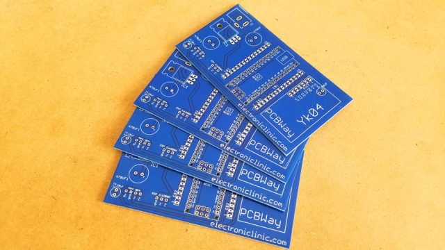
These are the PCBs, I received from the PCBWay Company, As you can see the Quality is really great. The silkscreen is quite clear and the solder mask looks amazing…
The components placement and Soldering:
I started off, by placing the components carefully, properly inserted all the required electronics into the PCB board and completed my soldering job.
![]()
This is how the PCB board looks after soldering.
Finally, I connected the GSM Module and GPS module as per the circuit diagram already explained. Our SMS GPS Security Tracking system is ready. Now let’s take a look at the Arduino programming.
Before, you start the programming; first of all, make sure you download all the necessary libraries.
SMS GPS Security Tracking System, Arduino Nano Programming:
|
1 2 3 4 5 6 7 8 9 10 11 12 13 14 15 16 17 18 19 20 21 22 23 24 25 26 27 28 29 30 31 32 33 34 35 36 37 38 39 40 41 42 43 44 45 46 47 48 49 50 51 52 53 54 55 56 57 58 59 60 61 62 63 64 65 66 67 68 69 70 71 72 73 74 75 76 77 78 79 80 81 82 83 84 85 86 87 88 89 90 91 92 93 94 95 96 97 98 99 100 101 102 103 104 105 106 107 108 109 110 111 112 113 114 115 116 117 118 119 120 121 122 123 124 125 126 127 128 129 130 131 132 133 134 135 136 137 138 139 140 141 142 143 144 145 146 147 148 149 150 151 152 153 154 155 156 157 158 159 160 161 162 163 164 165 166 167 168 169 170 171 172 173 174 175 176 177 178 179 180 181 182 183 184 185 186 187 188 189 190 191 192 193 194 195 196 197 198 199 200 201 202 203 204 205 206 207 208 209 210 211 212 213 214 215 216 217 218 219 220 221 222 223 224 225 226 227 228 229 230 231 232 233 234 235 236 237 238 239 240 241 242 243 244 245 246 247 248 249 250 251 252 253 254 |
#include <SoftwareSerial.h> #include <SimpleTimer.h> #include <stdlib.h> #include <TinyGPS++.h> static const int RXPin = 2, TXPin = 3; static const uint32_t GPSBaud = 9600; int m = 9740; int y = 71; // The TinyGPS++ object TinyGPSPlus gps; // The serial connection to the GPS device SoftwareSerial ss(RXPin, TXPin); // for gps SoftwareSerial SIM900(7, 8); // for gsm module int theft_Sensor = 4; // any digial sensor you want to use for detection String textForSMS; // Starts in Automatic Mode int Yk_D0 = 12; // wire from the D0 pin of the yk04 receiver, A on Remote controller int Yk_D0_Flag = 0; // Stops the automatic Mode int Yk_D1 = 11; // wire from the D1 pin of the yk04 receiver, B on Remote Controller // Anti-theft Mode int Yk_D2 = 10; // wire from the D2 pin of the yk04 receiver, C on Remote Controller int Yk_D2_Flag = 0; // Normal mode int Yk_D3 = 9; // wire from the D3 pin of the yk04 receiver, D on Remote Controller double longitude; double latitude; char buff[10]; String mylong = ""; // for storing the longittude value String mylati = ""; // for storing the latitude value SimpleTimer timer; int secs = 0; int minutes = 0; int mflag = 0; void setup() { SIM900.begin(19200); Serial.begin(9600); ss.begin(GPSBaud); delay(5000); // give time to log on to network. Serial.println(" logging time completed!"); randomSeed(analogRead(0)); pinMode(Yk_D0, INPUT); // automatic mode digitalWrite(Yk_D0, LOW); pinMode(Yk_D1, INPUT); // normal mode pinMode(Yk_D2, INPUT);// anti_theft mode pinMode(Yk_D3, INPUT);// Normal mode pinMode(theft_Sensor, INPUT_PULLUP); // Sensor connected with D4 of Arduino timer.setInterval(1000L, Send_GPS_Location); } void sendSMS(String message) { SIM900.print("AT+CMGF=1\r"); // AT command to send SMS message delay(100); SIM900.println("AT + CMGS = \"+923339537499\""); // recipient's mobile number, in international format delay(100); SIM900.println(message); // message to send delay(100); SIM900.println((char)26); // End AT command with a ^Z, ASCII code 26 delay(100); SIM900.println(); delay(5000); // give module time to send SMS } void loop() { // This sketch displays information every time a new sentence is correctly encoded. while (ss.available() > 0) if (gps.encode(ss.read())) displayInfo(); if (millis() > 5000 && gps.charsProcessed() < 10) { Serial.println(F("No GPS detected: check wiring.")); while(true); } // for the Yk_D0 which enables the automatic mode //***************************************************************** //**************************************************************** if(digitalRead(Yk_D0) == HIGH) // activates the automatic mode { Yk_D0_Flag = 1; } if(digitalRead(Yk_D1) == HIGH) // stops the automatic mode { Yk_D0_Flag = 0; secs = 0; minutes = 0; } if(Yk_D0_Flag == 1) { timer.run(); // activate the timer displayInfo(); if (mflag == 1) { displayInfo(); latitude = gps.location.lat(), 6 ; longitude = gps.location.lng(), 6 ; // for latitude mylati = dtostrf(latitude, 3, 6, buff); mylong = dtostrf(longitude, 3, 6, buff); //textForSMS = textForSMS + "Latitude:" + "," + mylati + "," + "Longitude: "+ mylong + ","; textForSMS = textForSMS + "http://www.google.com/maps/place/" + mylati + "," + mylong ; sendSMS(textForSMS); textForSMS = ""; Serial.println(textForSMS); Serial.println("message sent."); delay(3000); mflag = 0; } } // for the anti-theft if (digitalRead(Yk_D2) == HIGH) { Yk_D2_Flag = 1; } if (digitalRead(Yk_D3) == HIGH ) { Yk_D2_Flag = 0; } if ( (Yk_D2_Flag == 1) && ( digitalRead(theft_Sensor) == LOW) ) { timer.run(); // activate the timer displayInfo(); if (mflag == 1) { displayInfo(); latitude = gps.location.lat(), 6 ; longitude = gps.location.lng(), 6 ; // for latitude mylati = dtostrf(latitude, 3, 6, buff); mylong = dtostrf(longitude, 3, 6, buff); //textForSMS = textForSMS + "Latitude:" + "," + mylati + "," + "Longitude: "+ mylong + ","; textForSMS = textForSMS + "http://www.google.com/maps/place/" + mylati + "," + mylong ; sendSMS(textForSMS); textForSMS = ""; Serial.println(textForSMS); Serial.println("message sent."); delay(3000); mflag = 0; } } } void displayInfo() { Serial.print(F("Location: ")); if (gps.location.isValid()) { Serial.print(gps.location.lat(), 6); Serial.print(F(",")); Serial.print(gps.location.lng(), 6); Serial.print(" "); Serial.print(F("Speed:")); Serial.print(gps.speed.kmph()); } else { Serial.print(F("INVALID")); } Serial.print(F(" Date/Time: ")); if (gps.date.isValid()) { Serial.print(gps.date.month()); Serial.print(F("/")); Serial.print(gps.date.day()); Serial.print(F("/")); Serial.print(gps.date.year()); } else { Serial.print(F("INVALID")); } Serial.print(F(" ")); if (gps.time.isValid()) { if (gps.time.hour() < 10) Serial.print(F("0")); Serial.print(gps.time.hour()); Serial.print(F(":")); if (gps.time.minute() < 10) Serial.print(F("0")); Serial.print(gps.time.minute()); Serial.print(F(":")); if (gps.time.second() < 10) Serial.print(F("0")); Serial.print(gps.time.second()); Serial.print(F(".")); if (gps.time.centisecond() < 10) Serial.print(F("0")); Serial.print(gps.time.centisecond()); } else { Serial.print(F("INVALID")); } Serial.println(); } void Send_GPS_Location() { secs = secs + 1; Serial.println("Secs:"); Serial.println(secs); if ( secs >= 59 ) { minutes = minutes + 1; secs = 0; Serial.println("Minutes:"); Serial.println(minutes); if (minutes >= 2) { minutes = 0; secs = 0; mflag = 1; } } } |
SMS GPS Security Tracking System, Code Explanation:
I started off by adding all the libraries.
#include <SoftwareSerial.h>
#include <SimpleTimer.h>
#include <stdlib.h>
#include <TinyGPS++.h>
I defined pins for the GPS module and selected 9600 as the baud rate.
static const int RXPin = 2, TXPin = 3;
static const uint32_t GPSBaud = 9600;
Next, I defined pins for the GSM module and for the push button.
// The TinyGPS++ object
TinyGPSPlus gps;
// The serial connection to the GPS device
SoftwareSerial ss(RXPin, TXPin); // for gps
SoftwareSerial SIM900(7, 8); // for gsm module
int theft_Sensor = 4; // any digial sensor you want to use for detection
I also defined a variable textForSMS which is used for storing the string message.
String textForSMS;
I defined pins for the YK04 receiver module, which are used to select between the two modes.
// Starts in Automatic Mode
int Yk_D0 = 12; // wire from the D0 pin of the yk04 receiver, A on Remote controller
int Yk_D0_Flag = 0;
// Stops the automatic Mode
int Yk_D1 = 11; // wire from the D1 pin of the yk04 receiver, B on Remote Controller
// Anti-theft Mode
int Yk_D2 = 10; // wire from the D2 pin of the yk04 receiver, C on Remote Controller
int Yk_D2_Flag = 0;
// Normal mode
int Yk_D3 = 9; // wire from the D3 pin of the yk04 receiver, D on Remote Controller
Finally, I defined variables for storing the longitude, latitude, seconds, and minutes and also defined a timer.
double longitude;
double latitude;
char buff[10];
String mylong = “”; // for storing the longittude value
String mylati = “”; // for storing the latitude value
SimpleTimer timer;
int secs = 0;
int minutes = 0;
int mflag = 0;
Inside the void steup() function I activated the Serial communication and set all the pins as the input.
void setup()
{
SIM900.begin(19200);
Serial.begin(9600);
ss.begin(GPSBaud);
delay(5000); // give time to log on to network.
Serial.println(” logging time completed!”);
randomSeed(analogRead(0));
pinMode(Yk_D0, INPUT); // automatic mode
digitalWrite(Yk_D0, LOW);
pinMode(Yk_D1, INPUT); // normal mode
pinMode(Yk_D2, INPUT);// anti_theft mode
pinMode(Yk_D3, INPUT);// Normal mode
pinMode(theft_Sensor, INPUT_PULLUP); // Sensor connected with D4 of Arduino
timer.setInterval(1000L, Send_GPS_Location);
}
Send_GPS_Location is a user-defined function which is executed after every 1 second. I will talk about this in detail, in a minute.
sendSMS() function is a user-defined function, it has no return type and takes only one argument as the input which is of the type string. The purpose of this function is to send a message to a specific cell phone number.
void sendSMS(String message)
{
SIM900.print(“AT+CMGF=1\r”); // AT command to send SMS message
delay(100);
SIM900.println(“AT + CMGS = \”+923339539469\””); // recipient’s mobile number, in international format
delay(100);
SIM900.println(message); // message to send
delay(100);
SIM900.println((char)26); // End AT command with a ^Z, ASCII code 26
delay(100);
SIM900.println();
delay(5000); // give module time to send SMS
}
The actual code is placed inside the void loop() function.
if(digitalRead(Yk_D0) == HIGH) // activates the automatic mode
{
Yk_D0_Flag = 1;
}
if(digitalRead(Yk_D1) == HIGH) // stops the automatic mode
{
Yk_D0_Flag = 0;
secs = 0;
minutes = 0;
}
These two condition are used to check whether A or B button is pressed on the transmitter side and then accordingly change the Yk_D0_Flag value. If Button A is press the Yk_D0_Flag value is set to 1 and if button B is pressed then the Yk_D0_Flag value is set to 0 and also reset the seconds and minutes.
if(Yk_D0_Flag == 1)
{
timer.run(); // activate the timer
displayInfo();
if (mflag == 1)
{
displayInfo();
latitude = gps.location.lat(), 6 ;
longitude = gps.location.lng(), 6 ;
// for latitude
mylati = dtostrf(latitude, 3, 6, buff);
mylong = dtostrf(longitude, 3, 6, buff);
//textForSMS = textForSMS + “Latitude:” + “,” + mylati + “,” + “Longitude: “+ mylong + “,”;
textForSMS = textForSMS + “http://www.google.com/maps/place/” + mylati + “,” + mylong ;
sendSMS(textForSMS);
textForSMS = “”;
Serial.println(textForSMS);
Serial.println(“message sent.”);
delay(3000);
mflag = 0;
}
}
This condition checks if the flag value is 1, which means if button A is pressed on the transmitter. We activate the timer using the timer.run() function. Next call the displayInfo() function.
if (mflag == 1)
This condition is used to check if the mflag is set to 1. By default this flag is set to 0. When the timer is activated the Arduino starts counting the seconds and minutes. When the minutes are equal to the predefined value this flag is set to 1. So, if the mflag == 1 then read the latitude and longitude values, convert these values into string. We make a complete message consisting of the Google map URL link and then finally send the message, wait for 3 seconds and then make the mflag = 0. So this message will be sent after every 2 minutes until you press the button B on the transmitter which activates the normal mode.
if ( (Yk_D2_Flag == 1) && ( digitalRead(theft_Sensor) == LOW) )
The same technique is also used for the anti-theft mode. But this time a message is sent only if the Yk_D2_Flag value is set to 1 and also if the pushbutton is pressed.
displayInfo() function is used to read the GPS location…
Send_GPS_Location() is a user-defined function, this function is controlled using a timer. This function is used to count the seconds and minutes. Currently the value is set to 2. This means a message will be sent after every 2 minutes.
Testing the SMS GPS Security Tracking System:
I started off by powering up the device using the Lipo Battery, waited for a few seconds, my GSM module successfully connected with the network and the LED started blinking at a slower rate. When the GSM module is not connected with the network then the LED blinks fast. If your GSM module doesn’t connect, simply remove the SIM and insert it again. In some countries, the IMEI is also blocked. Make sure your GSM module is not blocked.
I performed all the initial tests, I was able to remotely trigger the controller and was able to successfully receive the messages consisting of Google’s Map URL link with the Latitude and Longitude values. You simply click on Google’s Map URL link the exact location is displayed with almost 4 feet to 1-meter accuracy. I kept checking this module and it worked perfectly without errors.
![]()
Watch Video Tutorial:
Discover more from Electronic Clinic
Subscribe to get the latest posts sent to your email.


