Arduino GSM Project: Security Alert message to multiple numbers
Last Updated on August 18, 2024 by Engr. Shahzada Fahad
Table of Contents
Description:
Arduino GSM Project: Security Alert message to multiple numbers-In this tutorial, you will learn how to make an Advanced security system and send the Security Alert message to multiple numbers using Arduino and A GSM Sim900A Module. For the demonstration purposes, I will be using an LDR, which makes this project as the laser security system, but if you want you can also replace the LDR with a PIR sensor or Magnetic reed switch Sensor or a limit switch and so on. You can also use multiple sensors.
This is basically the 2nd version of the GSM laser security system in which I used the LDR sensor for the intruder detection and I used the same GSM sim900A module. in this project, the security alert message is only sent to one number. If you want to watch this Tutorial.
But in many situations, we need to send the same security alert message to multiple numbers. So this tutorial is all about how to write a very simple program and how to connect all the components together to make the advanced security system. In this tutorial, we will cover
- GSM SIM900A module Pinout explanation
- Complete Circuit Diagram
- Arduino GSM project Programming and finally
- Testing
Without any further delay, let’s get started!!!
For the step by step explanation watch Video tutorial given in the end.
Amazon Links.
Arduino Nano USB-C Type (Recommended)
*Disclosure: These are affiliate links. As an Amazon Associate I earn from qualifying purchases.
GSM SIM900A module pinout:
Arduino GSM Project: Security Alert message to multiple numbers
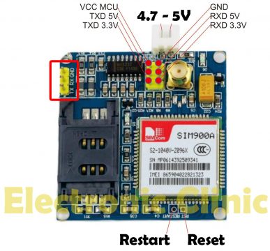
This is the GSM sim900A module, in the market, we have different types of GSM modules, the one I will be using today is GSM sim900A if you want you can also use any other gsm module, like for example sim900D. I have also tested the same programming using sim900D but with a different baud rate, the rest of the program remains the same. If you want to study more about the GSM Sim900A module then read my article “GSM sim900A Complete Guide“
If you are from Pakistan, Bangladesh or India make sure you double-check the GSM module and purchase the unlocked version of the sim900A module. This GSM sim900A module as you can see on the screen has no Onboard voltage regulator, so be careful while applying the voltage. Ideal voltage for this GSM module is 4.7v but you can also connect it with a 5v adaptor. If you don’t have a 5v adaptor then you can make your power supply using an lm317t adjustable variable voltage regulator, I have a very detailed tutorial on lm317t explaining everything. If in case you want to watch this tutorial.
As you can see clearly in the picture above this module has so many pins that are clearly labeled, but we will be using only 5 of these pins, the power supply pins, GND, Rxd 5v, and TXD 5v. The GND will be connected with the Arduino’s GND, TXD will be connected with the Arduino’s pin number 7 and RXD will be connected with the Arduino’s pin number 8.
Arduino GSM Project Circuit Diagram:

This schematic is designed in Cadesoft eagle 9.1.0 version, if you want to learn how to make schematics and PCB’s then you watch my tutorial.
Tx of the sim900A is connected with pin number 7 of the Arduino, the Rx pin of the sim900A module is connected with pin number 8 of Arduino, and GND is connected with the Arduino’s ground. a power supply is connected with the sim900A module ideal voltage is 4.7v to 5v as already explained.
An LDR is connected in series with a 10k resistor which makes a voltage divider circuit. As you know an LDR is basically a variable resistor, whose resistance changes with the amount of light falling on the LDR. So a change in resistance will result in a change in voltage. This change in voltage can be monitored using the analog pin A1 of the Arduino.
GSM Sim900A Module Interfacing with Arduino:

All the components are interfaced as per the circuit diagram, this is the LDR circuit, as you can see an LDR is connected in series with a 10k resistor. A wire from the middle of the LDR and 10k resistor is connected with the analog pin A1 of the Arduino.
The GSM sim900A module Txd and Rxd pins are connected with the Arduino pin number 7 and pin number 8, and make sure you connected the ground of the gsm module with the ground of the Arduino. This GSM module will be powered up using this Regulated 5v power supply. Now let’s discuss the Arduino Programming.
Arduino GSM Project Programming:
Arduino GSM Project: Security Alert message to multiple numbers
For the step by step program explanation watch video tutorial given at the end.
|
1 2 3 4 5 6 7 8 9 10 11 12 13 14 15 16 17 18 19 20 21 22 23 24 25 26 27 28 29 30 31 32 33 34 35 36 37 38 39 40 41 42 43 44 45 46 47 48 49 50 51 52 53 54 55 56 57 58 59 60 61 62 63 64 65 66 67 68 |
#include <SoftwareSerial.h> SoftwareSerial SIM900(7, 8); // gsm module connected here String textForSMS; int data = 0; int sensor = A1; // LDR is connected with the analog pin A1 of the Arduino // cell numbers to which you want to send the security alert message String f1001 = "+923351920959"; String f1002 = "+923108688660"; String f1003 = "+923339218213"; void setup() { randomSeed(analogRead(0)); Serial.begin(9600); SIM900.begin(9600); // original 19200. while enter 9600 for sim900A Serial.println(" logging time completed!"); pinMode(sensor, INPUT); delay(5000); // wait for 5 seconds } void loop() { data = analogRead(sensor); Serial.println(data); if ( data < 400) // { textForSMS = "\nIntruder detected"; //sendSMS(textForSMS); sendsms(textForSMS, f1001); // you can use a variable of the type String Serial.println(textForSMS); Serial.println("message sent."); delay(5000); sendsms("Intruder Detected!!!!!!!!!", f1002); // you can also write any message that you want to send. Serial.println(textForSMS); Serial.println("message sent."); delay(5000); sendsms("Intruder Detected!!!!!!!!!", f1003); // you can also write any message that you want to send. Serial.println(textForSMS); Serial.println("message sent."); delay(5000); } } void sendsms(String message, String number) { String mnumber = "AT + CMGS = \""+number+"\""; SIM900.print("AT+CMGF=1\r"); delay(1000); SIM900.println(mnumber); // recipient's mobile number, in international format delay(1000); SIM900.println(message); // message to send delay(1000); SIM900.println((char)26); // End AT command with a ^Z, ASCII code 26 delay(1000); SIM900.println(); delay(100); // give module time to send SMS // SIM900power(); } |
Watch Video Tutorial:
Other GSM-based Projects:
How to use GSM and Bluetooth Together To monitor Any Sensors wirelessly using Arduino
RFID & GSM based student Attendance Alert message to parents
Request Temperature Data Using GSM and Arduino
Arduino and Gsm based laser security system
Car accident location tracking using GSM, GPS, and Arduino
GSM Alarm System Using Arduino and a PIR Sensor
Arduino Gas leakage detection and SMS alert MQ-2 sensor
RFID based students attendance system with message Alert
Discover more from Electronic Clinic
Subscribe to get the latest posts sent to your email.


Hello 🙂
I need Your help.
I saw Your code about multiple sms send and I created this program code:
#define sensor 7
#include <SoftwareSerial.h>
SoftwareSerial SIM800(11, 12); // gsm module connected here
String textForSMS;
// cell numbers to which you want to send the security alert message
String f1001 = “+48694377xxx”;
String f1002 = “+48509168xxx”;
void setup() {
randomSeed(analogRead(0));
Serial.begin(9600);
SIM800.begin(9600); // original 19200. while enter 9600 for sim900A
Serial.println(” logging time completed!”);
pinMode(sensor, INPUT_PULLUP);
delay(5000); // wait for 5 seconds
}
void loop() {
{
textForSMS = “\nIntruder detected”;
//sendSMS(textForSMS);
sendsms(textForSMS, f1001); // you can use a variable of the type String
Serial.println(textForSMS);
Serial.println(“message sent.”);
delay(5000);
sendsms(“Intruder Detected!!!!!!!!!”, f1002); // you can also write any message that you want to send.
Serial.println(textForSMS);
Serial.println(“message sent.”);
delay(5000);
}
}
But it’s not working, please tell my why? I use module SIM800L: https://robu.in/wp-content/uploads/2017/09/GSM-MODULE-SIM800-5V.jpg
On serial port monitor I see every command from program arduion.
Please help me with this, and answer for email 🙂
Thank You very much.
Hello i make this project it’s working fine but i have problems when PIR sensor is High sms send continuous pls help me
i do the same program but it is not working is there any error?
there is no error, it’s fully tested. You can watch my video tutorial as well.