Car accident location tracking using GSM, GPS, and Arduino
Last Updated on August 18, 2024 by Engr. Shahzada Fahad
Table of Contents
Description:
Car accident location– In this tutorial, we are going to make our own car accident detection unit which can be easily fitted inside the DashBoard or bonnet of the car. Arduino GPS car accident location tracking system is completely based on the Neo 6m GPS module and SIM900A gsm module. The Arduino GPS car accident location tracking system can be used throughout the world.
About the Sponsor:
This article is sponsored by Wellpcb. Wellpcb is one of the top PCB’s manufacturing companies; they offer great quality and service. You can test their PCB quality only at 5 dollars for 5 PCB’s. You can ask for the price details by simply clicking on the PCB online quote, enter your PCB specifications, and click price. Once you are satisfied with their pricing then you can upload your Gerber files. Also, check out their other website ourpcb.
In the Car Accident Location tracking system, limit switches are used to detect if the car is hit. If the Car is hit a message is sent to the concerned person. The Cell Phone number used in the programming can be updated at any time.
For the Detailed step by step explanation, you can watch a Video Tutorial available at the end.
Amazon Links:
Arduino Nano USB-C Type (Recommended)
*Disclosure: These are affiliate links. As an Amazon Associate I earn from qualifying purchases.
SIM900A gsm Module:

This is the GSM module that I will be using in this tutorial, in the market we have different types of GSM modules, the one I will be using today is sim900A, the same code is also tested on sim900D, so if you want you can also use sim900D.
If you are from Pakistan, Bangladesh or India make sure you purchase the unlocked version of the sim900A. This GSM sim900A module the one we will be using in this tutorial, as you can see on the screen has no Onboard voltage regulator, so be careful while applying the voltage. Ideal voltage for this GSM module is 4.7v but you can also connect it with the 5v adaptor.
As the ideal voltage for this gsm module is 4.7v to 5volts, so any voltage above this can damage the gsm module. If you don’t have the regulated 5v adaptor then you can also use an lm317t adjustable voltage regulator. I have a very detailed tutorial on this.
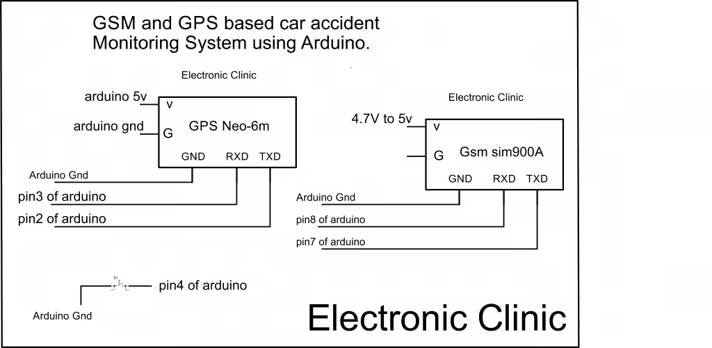
As you can see sim900A module has so many pins that are clearly labeled but we will be using only 5 of these pins, the power supply pins, GND, Rxd 5v, and txd 5v. The GND of the gsm sim900A module will be connected with the Arduino GND, TXD of the gsm sim900A will be connected with the Arduino pin7 and finally, the RXD of the gsm sim900A module will be connected with the Arduino pin8.
Neo 6M GPS Module used in Car accident location tracking:

This is the Neo-6M GPS module that we gonna be using in this Tutorial. This GPS module can be interfaced with the Arduino using VCC, rx, tx, and gnd. For the easy interfacing, we will need to solder 4 wires with this Neo 6M GPS module. For the Soldering watch Video Tutorial.
The Neo 6M GPS module needs 3 to 5v. I will use the Arduino’s 5v and its default baud rate is 9600 which we will be using in the programming.
Circuit Diagram of the Car accident location tracking:
This is the complete circuit diagram of the Arduino GPS car accident location tracking system.
This schematic is designed in cadesoft eagle, if you want to learn how to make schematics and pcb’s then you can watch my tutorials visit my YouTube channel “Electronic Clinic”. The Neo-6MGPS and gsm sim900A modules interfacing with Arduino is very simple. As you can see in the circuit diagram the VCC of the GPS module is connected with 5v, Rx will be connected with pin3 of the Arduino, tx will be connected with pin2 of the Arduino and Gnd will be connected with the Arduino GND.
tx of the sim900A is connected with pin7 of Arduino, Rx of the sim900A is connected with pin8 of Arduino and is connected with the GND of Arduino. A power supply is connected with sim900A ideal voltage is 4.7v to 5v.
The limit switch is connected with pin4 of the Arduino, so when the limit switch is activated it will give 0 zero “gnd” as a signal to the Arduino this signal means that the car is hit.
Car accident location tracking Arduino Programming:
|
1 2 3 4 5 6 7 8 9 10 11 12 13 14 15 16 17 18 19 20 21 22 23 24 25 26 27 28 29 30 31 32 33 34 35 36 37 38 39 40 41 42 43 44 45 46 47 48 49 50 51 52 53 54 55 56 57 58 59 60 61 62 63 64 65 66 67 68 69 70 71 72 73 74 75 76 77 78 79 80 81 82 83 84 85 86 87 88 89 90 91 92 93 94 95 96 97 98 99 100 101 102 103 104 105 106 107 108 109 110 111 112 113 114 115 116 117 118 119 120 121 122 123 124 125 126 127 128 129 130 131 132 133 134 135 136 137 138 139 140 141 142 143 144 145 146 147 148 149 150 151 152 153 154 155 156 157 158 159 160 161 162 163 164 165 166 167 168 169 170 171 172 173 174 175 176 177 178 179 180 181 182 183 184 185 186 187 188 189 190 191 192 193 194 195 196 197 198 199 200 201 202 203 204 205 206 207 208 209 210 211 212 213 214 215 216 217 |
// Arduino gps car accident location tracking system using Neo 6m gps module and sim900A //gsm module. #include <SoftwareSerial.h> #include <TinyGPS++.h> static const int RXPin = 2, TXPin = 3; static const uint32_t GPSBaud = 9600; int m = 9740; int y = 71; // The TinyGPS++ object TinyGPSPlus gps; // The serial connection to the GPS device SoftwareSerial ss(RXPin, TXPin); // for gps SoftwareSerial SIM900(7, 8); // for gsm module int sensor = A1; // tilt sensor connected here int led = 13; // tilt sensor output indication String textForSMS; int limits = 4; // limit switch String datareal; String dataimaginary; String combined; int raw = 1000000; String datareal2; String dataimaginary2; String combined2; double longitude; double latitude; void setup() { SIM900.begin(19200); Serial.begin(9600); ss.begin(GPSBaud); delay(10000); // give time to log on to network. Serial.println(" logging time completed!"); randomSeed(analogRead(0)); pinMode(limits, INPUT); digitalWrite(limits, HIGH); pinMode(sensor, INPUT); pinMode(led, OUTPUT); digitalWrite(led, LOW); Serial.println(F("DeviceExample.ino")); Serial.println(F("A simple demonstration of TinyGPS++ with an attached GPS module")); Serial.print(F("Testing TinyGPS++ library v. ")); Serial.println(TinyGPSPlus::libraryVersion()); Serial.println(); } void sendSMS(String message) { SIM900.print("AT+CMGF=1\r"); // AT command to send SMS message delay(100); SIM900.println("AT + CMGS = \"+923339218213\""); // recipient's mobile number, in international format delay(100); SIM900.println(message); // message to send delay(100); SIM900.println((char)26); // End AT command with a ^Z, ASCII code 26 delay(100); SIM900.println(); delay(5000); // give module time to send SMS } void loop() { int reading; reading = analogRead(sensor); // Serial.println(reading); // delay(1000); // for the tilt sensor //***************************************************************** //**************************************************************** if(reading > 800) { digitalWrite(led, HIGH); displayInfo(); latitude = gps.location.lat(), 6 ; longitude = gps.location.lng(), 6 ; // for latitude long datareal = int(latitude); int fahad = ( latitude - datareal) * 100000; // for longitude long datareal2 = int(longitude); int fahad2 = (longitude - datareal2 ) * 100000; textForSMS = "Longitude: "; textForSMS.concat(datareal2); textForSMS = textForSMS + "."; textForSMS.concat(fahad2); textForSMS = textForSMS + " Latitude: "; textForSMS.concat(datareal); textForSMS = textForSMS + "."; textForSMS.concat(fahad); textForSMS = textForSMS + " Electronic Clinic, Tilt sensor controlled section"; sendSMS(textForSMS); Serial.println(textForSMS); Serial.println("message sent."); delay(5000); } // This sketch displays information every time a new sentence is correctly encoded. while (ss.available() > 0) if (gps.encode(ss.read())) displayInfo(); if (millis() > 5000 && gps.charsProcessed() < 10) { Serial.println(F("No GPS detected: check wiring.")); while(true); } // for the button //***************************************************************** //**************************************************************** if(digitalRead(limits) == LOW) { displayInfo(); latitude = gps.location.lat(), 6 ; longitude = gps.location.lng(), 6 ; // for latitude long datareal = int(latitude); int fahad = ( latitude - datareal) * 100000; // for longitude long datareal2 = int(longitude); int fahad2 = (longitude - datareal2 ) * 100000; textForSMS = "Longitude: "; textForSMS.concat(datareal2); textForSMS = textForSMS + "."; textForSMS.concat(fahad2); textForSMS = textForSMS + " Latitude: "; textForSMS.concat(datareal); textForSMS = textForSMS + "."; textForSMS.concat(fahad); textForSMS = textForSMS + " Electronic Clinic; Limit Switch1 activated"; sendSMS(textForSMS); Serial.println(textForSMS); Serial.println("message sent."); delay(5000); } else digitalWrite(limits, HIGH); digitalWrite(led, LOW); } void displayInfo() { Serial.print(F("Location: ")); if (gps.location.isValid()) { Serial.print(gps.location.lat(), 6); Serial.print(F(",")); Serial.print(gps.location.lng(), 6); Serial.print(" "); Serial.print(F("Speed:")); Serial.print(gps.speed.kmph()); } else { Serial.print(F("INVALID")); } Serial.print(F(" Date/Time: ")); if (gps.date.isValid()) { Serial.print(gps.date.month()); Serial.print(F("/")); Serial.print(gps.date.day()); Serial.print(F("/")); Serial.print(gps.date.year()); } else { Serial.print(F("INVALID")); } Serial.print(F(" ")); if (gps.time.isValid()) { if (gps.time.hour() < 10) Serial.print(F("0")); Serial.print(gps.time.hour()); Serial.print(F(":")); if (gps.time.minute() < 10) Serial.print(F("0")); Serial.print(gps.time.minute()); Serial.print(F(":")); if (gps.time.second() < 10) Serial.print(F("0")); Serial.print(gps.time.second()); Serial.print(F(".")); if (gps.time.centisecond() < 10) Serial.print(F("0")); Serial.print(gps.time.centisecond()); } else { Serial.print(F("INVALID")); } Serial.println(); } |
Watch Video Tutorial:
Other GPS Related Projects:
Arduino Neo 6m GPS module Interfacing, Programming, Library
Nodemcu GPS Tracker using Arduino Nodemcu esp8266 and Blynk
Discover more from Electronic Clinic
Subscribe to get the latest posts sent to your email.


