Ultrasonic sensor, Servo motor, and Arduino interfacing with MATLAB
Table of Contents
Description:
Ultrasonic sensor, servo motor, and Arduino interfacing with MATLAB– In this tutorial we are using ultrasonic sensor HC-SR40T, Servo motor, and Arduino with MATLAB. The servo motor will be used for the rotation of the ultrasonic sensor and the data will be send to the Arduino and from the Arduino data will be send to the MATLAB. Checkout some of my intermediate and advanced level projects on Arduino and Matlab.
Components Required:
We will require the following components for this project:
- Ultrasonic sensor HC-SR40T
- Arduino UNO
- Servo motor
Amazon Links:
Other Tools and Components:
Super Starter kit for Beginners
PCB small portable drill machines
*Please Note: These are affiliate links. I may make a commission if you buy the components through these links. I would appreciate your support in this way!
Arduino Matlab Project Circuit Diagram:
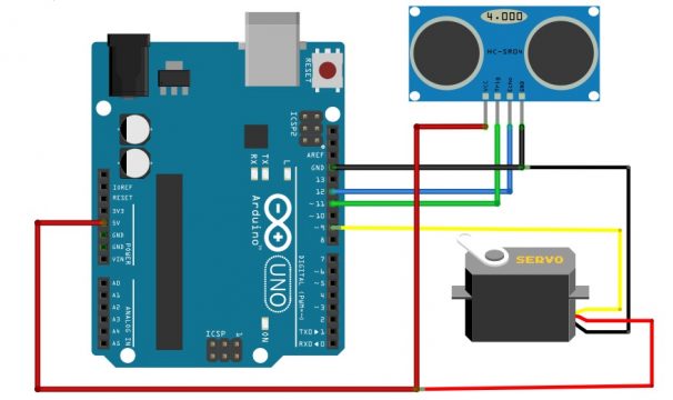
So let’s see the connection used in our project as we know that the ultrasonic sensor consists of four pins which are:
- VCC
- Ground
- Echo
- Trigger
So in order to connect the ultrasonic sensor with the Arduino we will perform the following steps:
- Connect the ground of the ultrasonic sensor with the ground of the Arduino
- Connect the VCC of the ultrasonic sensor with the 5V of the Arduino
- Connect the Echo pin of the ultrasonic sensor with the digital pin 11 of the Arduino
- Connect the trigger pin of the ultrasonic sensor with the digital pin 12 of the Arduino
Now in order to connect the servo motor to the Arduino:
- Connect the VCC of the servo motor with the 5V of Arduino
- Connect the ground of the servo motor with the ground of the Arduino
- Connect the signal wire with the digital pin 9 of the Arduino
For the VCC we can also use the external power supply for the servo motor because the servo motors is consume huge amount of current while starting search which may damage our Arduino board.
Arduino code for the Ultrasonic sensor and servo motor:
First of all we will includethe servo motor library
|
1 |
#include <Servo.h> |
Then we have created servo object with the name myservo
|
1 |
Servo myservo; |
Then we have declared some variables which are:
CM for the storing distance, duration for storing the time and pos for storing the position of the servo motor. Duration will store the time of the generated ultrasonic pulse which will go and return back to the sensor and CM will store the distance of the obstacle.
|
1 2 3 |
intpos = 0; long duration, cm ; |
As we have connected the ultrasonic sensor with the digital pin 11 and 12 so we will declare it as:
|
1 2 3 |
inttrigPin = 11; intechoPin = 12; |
In the setup we have defined the pin 9 to which a servo motor will be attached then we have started the serial monitor and declare the trigPin as OUTPUT and echoPin as input.
|
1 2 3 4 5 6 7 8 9 10 11 12 13 14 15 |
void setup() { //Serial Port begin myservo.attach(9); Serial.begin (9600); //Define inputs and outputs pinMode(trigPin, OUTPUT); pinMode(echoPin, INPUT); } |
Now in the loop function we have started a servo motor to rotate from 0 to 180 degree with a gap of four degrees then we have generated an ultrasonic pulse and then we have calculated the duration and the distance of the obstacle and we have stored this in the variable duration and cm. Then we have print these variables onto the serial monitor of the Arduino.
|
1 2 3 4 5 6 7 8 9 10 11 12 13 14 15 16 17 18 19 20 21 22 23 24 25 |
for (pos = 0; pos<= 180; pos += 4) { myservo.write(pos); digitalWrite(trigPin, LOW); delayMicroseconds(5); digitalWrite(trigPin, HIGH); delayMicroseconds(10); digitalWrite(trigPin, LOW); pinMode(echoPin, INPUT); duration = pulseIn(echoPin, HIGH); cm = (duration/2) / 29.1; Serial.println(pos); Serial.println(cm); delay(400); |
Arduino Complete code:
|
1 2 3 4 5 6 7 8 9 10 11 12 13 14 15 16 17 18 19 20 21 22 23 24 25 26 27 28 29 30 31 32 33 34 35 36 37 38 39 40 41 42 43 44 45 46 47 48 49 50 51 52 53 54 55 56 57 58 59 60 61 |
#include <Servo.h> Servo myservo; intpos = 0; inttrigPin = 11; intechoPin = 12; long duration, cm ; void setup() { //Serial Port begin myservo.attach(9); Serial.begin (9600); //Define inputs and outputs pinMode(trigPin, OUTPUT); pinMode(echoPin, INPUT); } void loop() { for (pos = 0; pos<= 180; pos += 4) { myservo.write(pos); digitalWrite(trigPin, LOW); delayMicroseconds(5); digitalWrite(trigPin, HIGH); delayMicroseconds(10); digitalWrite(trigPin, LOW); pinMode(echoPin, INPUT); duration = pulseIn(echoPin, HIGH); cm = (duration/2) / 29.1; Serial.println(pos); Serial.println(cm); delay(400); } } |
Interfacing Arduino with MATLAB:
First of all we will write the following command in order to clear all the variables and figures in the MATLAB.
|
1 2 3 4 5 |
clear all close all clc |
Then we established serial communication with the Arduino board using the command in which we will define the port number , baud rate and rate of the serial communication which we have define in the Arduino code and write the fopen command to initiate the Arduino communication
|
1 2 3 |
arduino=serial('COM3','BaudRate',9600); fopen(arduino); % initiate arduino communication |
We have also prepared two variables and initialized each of them to zero the CM and the POS.
|
1 2 3 |
CM(1)=0; pos(1)=0; |
Then we have written our while loop which works until our servo motor reached the angle of 180 degree and inside this loop we have given the position of the servo motor as well as the reading of the ultrasonic sensor from the serial monitor of the Arduino.Also we have made a table in which we have stores each of these variables that is the position of the servo motor as well as the reading of the ultrasonic sensor.
|
1 2 3 4 5 6 7 8 9 10 11 12 13 14 15 16 17 |
while (pos(1) < 180) pos(2) = fscanf(arduino,'%f'); CM(2)=fscanf(arduino,'%f'); pos(1)= pos(2); CM(1)=CM(2); table(i,1) = pos(1); table(i,2) = CM(1); i=i+1; end |
After this while loop ends we have created a polar plot of our surroundings we have written polar to plot the data on the graph also given the title to a map switch on the grid and at last we have ended the communication with our Arduino by writing fclosecommad.
|
1 2 3 4 5 6 7 |
polar(table(:,1)*pi/180, table (:,2)); title('Map of the Environment'); gridon; fclose(arduino); % end communication with arduino |
Complete MATLAB code:
|
1 2 3 4 5 6 7 8 9 10 11 12 13 14 15 16 17 18 19 20 21 22 23 24 25 26 27 28 29 30 31 32 33 34 35 36 37 38 39 40 41 |
clearall closeall clc arduino=serial('COM3','BaudRate',9600); fopen(arduino); % initiate arduino communication CM(1)=0; pos(1)=0; i=1; while (pos(1) < 180) pos(2) = fscanf(arduino,'%f'); CM(2)=fscanf(arduino,'%f'); pos(1)= pos(2); CM(1)=CM(2); table(i,1) = pos(1); table(i,2) = CM(1); i=i+1; end polar(table(:,1)*pi/180, table (:,2)); title('Map of the Environment'); gridon; fclose(arduino); % end communication with arduino |
Now our project is completed first of all we will upload the code to the Arduino then we will open the MATLAB and now in the MATLAB window run your MATLAB code to start the demonstration of the project. The servo motor will start rotation it is going from zero degree to 180 degree with gap of four degree each it is taking the reading of the obstacle which will come in front of it and the data will be plotted in the MATLAB.


