VL53L0X Arduino Interfacing and Programming
Last Updated on August 17, 2024 by Engr. Shahzada Fahad
Table of Contents
VL53L0X Sensor, Descriptions:
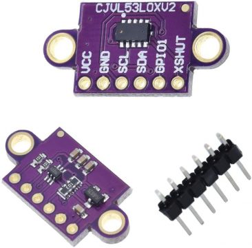
VL53L0X Arduino Interfacing and Programming- Unlike the other Ultrasonic Sensors and ToF10120 Laser Rangefinder, the VL53L0X can also be used for the object or obstacle detection. This sensor can measure distances of up to 2 meters with a resolution of one millimeter and it can be operated from 2.6 to 3.5 volts. Which makes it an ideal sensor and can be used with 3.3V compatible controller boards “STM32, ESP32, ESP8266, etc” and can also be used with 5V controller boards like Arduino, etc. It uses a 940 nanometer infrared emitter which is invisible to the human eye and it is also eye safe meaning that it will not cause any damage to your vision. You will see a couple of components which take care of the voltage level conversion this means that we can directly powered the sensor using 3.3 volts or 5 volts and that we can also interface it to a microcontroller that works on either 3.3 volts or 5 volts and this greatly simplifies things for us. On the top side, we have the sensor and the header pins that will be used for interfacing. It uses i2c for communication which means that we only need a total of four pins for operation. The XSHUT pin can be used to keep the sensor in the reset state, it is active low which means that you will need to connect it to ground to reset the sensor. GPIO1 is an interrupt pin that can be used to send the signal to the microcontroller to notify when the measurement is complete. Please check to see if there is any protective film over the sensor and if so then you will need to remove it in order to get the correct readings.
Ranging measurements are available through the sensors I²C (TWI) interface, which is also used to configure sensor settings,and the sensor provides two additional pins: a shutdown input and an interrupt output. The VL53L0X is a great IC, but its small, leadless, LGA package makes it difficult for the typical student or hobbyist to use. It also operates at a recommended voltage of 2.8 V, which can make interfacing difficult for microcontrollers operating at 3.3 V or 5 V.
Our breakout board addresses these issues, making it easier to get started using the sensor, while keeping the overall size as small as possible.
Amazon Links:
Arduino Nano USB-C Type (Recommended)
*Disclosure: These are affiliate links. As an Amazon Associate I earn from qualifying purchases.
VL53L0X

VL53L0X PIN Description:
VDD Regulated 2.8 V output. Almost 150 mA is available to power external components. (If you want to bypass the internal regulator,you can instead use this pin as a 2.8 V input with VIN disconnected.)
VIN: This is the main 2.6 V to 5.5 V power supply connection. The SCL and SDA level shifters pull the I²C lines high to this level.
GND: The ground (0 V) connection for your power supply. Your I²C control source must also share a common ground with this board.
SDA Level-shifted I²C data line: HIGH is VIN, LOW is 0 V
SCL Level-shifted I²C clock line: HIGH is VIN, LOW is 0 V
XSHUT This pin is an active-low shutdown input; the board pulls it up to VDD to enable the sensor by default. Driving this pin lowputs the sensor into hardware standby. This input is not level-shifted.
VL53LOX VS Ultrasonic sensor:
We have used the ultrasonic sensor before which is also used to measure distance the principle is the same for the two sensors. They both emit a signal and determine the time it takes for this signal to bounce back and get received, by knowing the time it takes for this signal to complete a round-trip. You can determine the distance between the sensor and any object that’s placed in front of it.
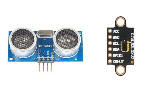
The ultrasonic sensor uses sound we that are in the 40 kilohertz frequency range while the Lidar sensor emits light that has a wavelength of about 940 nanometers one thing to keep a note off is that since we are using light the measurement cone is going to be much narrow when compared to the ultrasonic sensor. A quick comparison between the two sensors is that the ultrasonic sensor can measure up to four meters while the Lidar sensor is limited to about 2 meters at the low end. The ultrasonic sensor starts at about two centimeters while the Lidar starts about three centimeters. The ultrasonic sensor module only works at five volts while the Lidar module can work at either 3.3 volts or 5 volts. The ultrasonic sensor also uses PWM for both control and the output signal while the Lidar uses i2c for communication which simplifies things a bit. Finally the ultrasonic sensor weighs about 8.5 grams while the Lidar sensor weighs about 1.15 grams and both these were measured with the header pins.
VL53L0X sensor interfacing with Arduino:
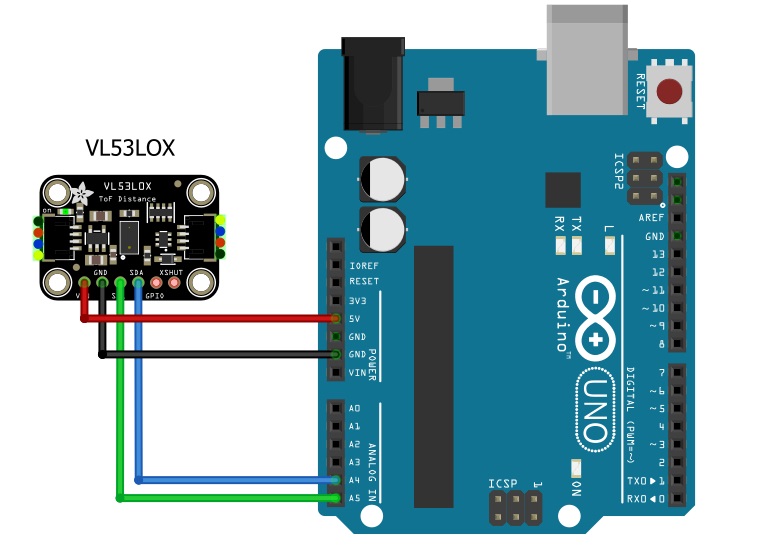
- Connect the VCC of the VL53L0X sensor with 5V of the Arduino
- Connect the ground of the VL53L0X sensor with the ground of the Arduino
- Connect the SDA pin of the VL53L0X sensor with analog pin A4 of the Arduino which is I2C SDA pin
- Connect SCL pin of the VL53L0X sensor with the analog pin A5 of the Arduino
VL53L0X Arduino Programming:
Now for coding first of all we will insert the VL53L0X library.
Open the Arduino IDE and go to the sketch, now in sketch click on the add zip library and insert the zip library of VL53L0X.

Now after installing the library go to file menu and in file menu click on examples and in examples click on the VL53L0X and now click on Single code will open.

|
1 2 3 4 5 6 7 8 9 10 11 12 13 14 15 16 17 18 19 20 21 22 23 24 25 26 27 28 29 30 31 32 33 34 35 36 37 38 39 40 41 42 43 44 45 46 47 48 49 50 51 52 53 54 55 56 57 58 59 |
#include <Wire.h> #include <VL53L0X.h> VL53L0X sensor; // Uncomment this line to use long range mode. This // increases the sensitivity of the sensor and extends its // potential range, but increases the likelihood of getting // an inaccurate reading because of reflections from objects // other than the intended target. It works best in dark // conditions. //#define LONG_RANGE // Uncomment ONE of these two lines to get // - higher speed at the cost of lower accuracy OR // - higher accuracy at the cost of lower speed //#define HIGH_SPEED //#define HIGH_ACCURACY void setup() { Serial.begin(9600); Wire.begin(); sensor.setTimeout(500); if (!sensor.init()) { Serial.println("Failed to detect and initialize sensor!"); while (1) {} } #if defined LONG_RANGE // lower the return signal rate limit (default is 0.25 MCPS) sensor.setSignalRateLimit(0.1); // increase laser pulse periods (defaults are 14 and 10 PCLKs) sensor.setVcselPulsePeriod(VL53L0X::VcselPeriodPreRange, 18); sensor.setVcselPulsePeriod(VL53L0X::VcselPeriodFinalRange, 14); #endif #if defined HIGH_SPEED // reduce timing budget to 20 ms (default is about 33 ms) sensor.setMeasurementTimingBudget(20000); #elif defined HIGH_ACCURACY // increase timing budget to 200 ms sensor.setMeasurementTimingBudget(200000); #endif } void loop() { Serial.print(sensor.readRangeSingleMillimeters()); if (sensor.timeoutOccurred()) { Serial.print(" TIMEOUT"); } Serial.println(); } |
Now after uploading the code to the Arduino UNO, You will be able to see the output of the sensor on the Serial Monitor.
Ultrasonic Sensor Related Projects:
Obstacle detection with HC-SR04 Ultrasonic Sensor
Safe Distance maintaining Robot Car
Bi-directional visitors counter
Hand Washing Timer Project using Arduino and Ultrasonic Sensor
Ultrasonic Sensor with Raspberry Pi
IoT based Flood Monitoring System using Ultrasonic Sensor and ESP8266
Smart Dustbin using Arduino and Ultrasonic Sensor
IoT based Water level Monitoring System
ToF10120 Related projects:
Distance measurement with ToF10120 Laser RangeFinder and Arduino
IoT Water Level Monitoring using ToF10120 and ESP8266
Car parking system using Arduino and ToF10120 Laser distance sensor
IoT water level monitoring using ESP32 and ToF10120 Sensor
Discover more from Electronic Clinic
Subscribe to get the latest posts sent to your email.


