Safe distance maintaining Car to Avoid accident using Ultrasonic Sensor
Table of Contents
Safe Distance maintaining Robot Car Description:
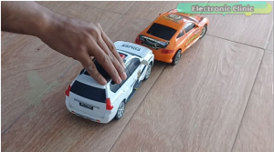
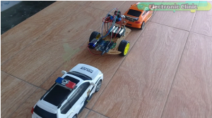
In this tutorial, you will learn how to make an automatic safe distance maintaining Robot Car. A control system for a Car to avoid accidents using the Ultrasonic sensor and Arduino Uno. With the help of such a control system, the car speed is automatically adjusted depending on the distance. This control system is entirely based on the Arduino, Ultrasonic Sensor, and L298N motor driver. In this Tutorial, I will also explain what safe distance is, and how safe distance maintaining technology can be used in real cars. I will share with you two methods that can be used in real cars, which will help you stay safe. You can also read my article on “how to reduce distracted driving accidents using driver drowsiness detection system“.
This is the 4th version of the Robot Car. While in the 3rd version
I used the flex sensor and the joystick together to control the same robot car, in this project the flex sensor was used as the accelerator and the joystick was used to control the car’s forward, left, right and reverse movement, I named this project as wireless hand gesture + joystick robot car…
While in the 2nd version
I used only the joystick to control the speed and movement of the robot Car. The program used in this project was a little bit complex, so that’s why I decided to make another version of this robot and use a separate sensor for the speed controlling. So that’s why I created version 3.
While in the first version
I used an Android cell phone to control the Robot Car using the hc-05 Bluetooth module.
This Tutorial is based on my previous tutorials,L298N Motor driver Getting Started tutorial:
in this tutorial I explained, how to assemble the robot parts and how to use the L298N motor driver to control the forward, left , right, and reverse movement. In this tutorial, I also explained how to control the speed of a dc motor using the pulse width modulation. …
If you are a beginner and you have never used the L298N motor driver then I highly recommend you should first watch this tutorial and then you can resume from here.
Amazon Links:
Arduino Nano USB-C Type (Recommended)
Other Tools and Components:
ESP32 WiFi + Bluetooth Module (Recommended)
Super Starter kit for Beginners
PCB small portable drill machines
DISCLAIMER:
Please Note: these are affiliate links. I may make a commission if you buy the components through these links. I would appreciate your support in this way!
Safe Distance:
You may already know the danger of following a car too closely as a violation of the law and how frequently it causes accidents..In this tutorial, we will focus on how to avoid this problem. You will learn how to judge a safe following distance,
so that you can always maintain enough space in front of you whenever you drive, to picture this space in your minds eyes, think of it as a space cushion as it is often called.
Following distance is defined as the distance between you and the vehicle in front of you when you are both moving on the road way.
When driving you must always be prepared for the car in front of you to stop, slow down or react to unexpected road conditions ahead. It could be that the vehicle in front of you is slowing for stop traffic in front of them or reacting to traffic signals, children, animals etc.
In the past say when your parents were learning to drive, the way that the idea of a space cushion was generally taught in driver education classes was in terms of car lengths. So for example you would have learned that there should be roughly one full car length between you and the car in front of you for every 10 miles per hour of speed that you are traveling.
So if you are traveling at 50 miles per hour you should be five car lengths behind the car in front of you..Driving Professionals finally realized that for most of us figuring out how many car lengths you are behind another car is really difficult…
To solve this problem you will need to make an automatic system that can measure the distance between you and the car in front of you. For distance measurement, we can use the Ultrasonic sensor. The ultrasonic sensor with Arduino can be used in different ways. For example
-
- You can make an automatic deceleration system. As the distance between you and the car in front of you decreases, your car speed will automatically reduce to maintain the safe distance. Now implementing this technology on real cars can be really difficult without the help of skilled programmers and mechanical experts, as this will require some changes in the car mechanical system. So don’t try this on a real car, but you can use this on a robot car to understand this concept.
ii. you can use some LEDs. Let’s say for every 1 meter of the distance you can light up one led. As a normal ultrasonic sensor is capable of measuring the distance up to 5 meters, it means you can use 5 LEDs. so this way you know exactly how far you are from the car in front of you and then manually you can increase or decrease the speed. Now you can try this by yourself as its safe.
3. Or you can use a buzzer that is activated when the distance between you and the car in front of you is less than 5 meters. This method works best in situations when you are not looking at the LEDs. So method number 2 and 3 can be combined together and can be implemented in real cars without any problem.
Using LEDs and buzzer are very simple, which you can do by yourself and these two methods can be used in real cars without any problems and it won’t need any changes in the car control system. In this episode I will show you how to make an automatic deceleration system for a robot car, just to present to you how cool it would be if this technology is implemented in every car.
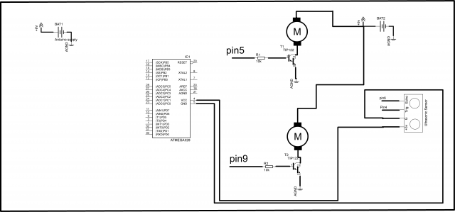
Interfacing motors and Ultrasonic Sensor with Arduino:
For the connections explanation watch video Tutorial.
Safe distance maintaining car Circuit Diagram:
Safe distance maintaining car Arduino Programming:
For the step by step program explanation watch video given at the end of this Article. If you have any questions let me know in a comment.
|
1 2 3 4 5 6 7 8 9 10 11 12 13 14 15 16 17 18 19 20 21 22 23 24 25 26 27 28 29 30 31 32 33 34 35 36 37 38 39 40 41 42 43 44 45 46 47 48 49 50 51 52 53 54 55 56 57 58 59 60 61 62 63 64 65 66 67 68 69 70 71 72 73 74 75 |
#define trigpin 4 // digital pin 4 #define echopin 3 // digital pin 3 int ena = 5; int enb = 6; int in1 = 8; int in2 = 9; int in3 = 10; int in4 = 11; float distancem; void setup() { Serial.begin(9600); pinMode(trigpin, OUTPUT); pinMode(echopin, INPUT); pinMode(ena, OUTPUT); pinMode(enb, OUTPUT); pinMode(in1, OUTPUT); pinMode(in2, OUTPUT); pinMode(in3, OUTPUT); pinMode(in4, OUTPUT); analogWrite(ena, 0); analogWrite(enb, 0); delay(1000); } void loop() { int duration, distance; digitalWrite(trigpin, HIGH); delayMicroseconds(1000); digitalWrite(trigpin, LOW); duration = pulseIn(echopin,HIGH); distance = ( duration / 2) / 29.1; Serial.println("inches:"); Serial.println(distance); distance = map(distance, 0 , 197, 0 , 255 ); if( (distance < 0) ) { distance = 0; } else if( (distance >= 0) && (distance <= 40) ) { analogWrite(ena, 0); analogWrite(enb, 0); digitalWrite(in1, LOW); digitalWrite(in2, LOW); digitalWrite(in3, LOW); digitalWrite(in4, LOW); } else if( distance > 40 ) { analogWrite(ena, distance); analogWrite(enb, distance); digitalWrite(in1, HIGH); digitalWrite(in2, LOW); digitalWrite(in3, LOW); digitalWrite(in4, HIGH); } } |
Program 2: Led’s Controlling
|
1 2 3 4 5 6 7 8 9 10 11 12 13 14 15 16 17 18 19 20 21 22 23 24 25 26 27 28 29 30 31 32 33 34 35 36 37 38 39 40 41 42 43 44 45 46 47 48 49 50 51 52 53 54 55 56 57 58 59 60 61 62 63 64 65 66 67 68 69 70 71 72 73 74 75 76 77 78 79 80 81 82 83 84 85 86 87 88 89 90 91 92 93 94 95 96 97 98 99 100 101 102 103 104 105 106 107 108 109 110 111 112 113 114 115 116 117 118 119 120 121 122 123 124 125 126 127 128 129 130 131 132 133 134 135 136 137 138 139 140 141 142 143 144 |
#define trigpin 4 // digital pin 4 #define echopin 3 // digital pin 2 int ena = 5; int enb = 6; int in1 = 8; int in2 = 9; int in3 = 10; int in4 = 11; int led1 = A0; int led2 = A1; int led3 = A2; int led4 = A3; int led5 = A4; float distancem; void setup() { Serial.begin(9600); pinMode(trigpin, OUTPUT); pinMode(echopin, INPUT); pinMode(ena, OUTPUT); pinMode(enb, OUTPUT); pinMode(in1, OUTPUT); pinMode(in2, OUTPUT); pinMode(in3, OUTPUT); pinMode(in4, OUTPUT); pinMode(led1, OUTPUT); pinMode(led2, OUTPUT); pinMode(led3, OUTPUT); pinMode(led4, OUTPUT); pinMode(led5, OUTPUT); digitalWrite(led1, LOW); digitalWrite(led2, LOW); digitalWrite(led3, LOW); digitalWrite(led4, LOW); digitalWrite(led5, LOW); analogWrite(ena, 0); analogWrite(enb, 0); delay(1000); } void loop() { int duration, distance; digitalWrite(trigpin, HIGH); delayMicroseconds(1000); digitalWrite(trigpin, LOW); duration = pulseIn(echopin,HIGH); distance = ( duration / 2) / 29.1; Serial.println("inches:"); Serial.println(distance); distance = map(distance, 0 , 197, 0 , 255 ); if( (distance < 0) ) { distance = 0; } else if( (distance >= 0) && (distance <= 40) ) { digitalWrite(led1, LOW); digitalWrite(led2, LOW); digitalWrite(led3, LOW); digitalWrite(led4, LOW); digitalWrite(led5, LOW); } else if( (distance > 40) && (distance <= 57) ) { digitalWrite(led1, HIGH); digitalWrite(led2, LOW); digitalWrite(led3, LOW); digitalWrite(led4, LOW); digitalWrite(led5, LOW); } else if( (distance > 57) && (distance <= 74) ) { digitalWrite(led1, HIGH); digitalWrite(led2, HIGH); digitalWrite(led3, LOW); digitalWrite(led4, LOW); digitalWrite(led5, LOW); } else if( (distance > 70) && (distance <= 91) ) { digitalWrite(led1, HIGH); digitalWrite(led2, HIGH); digitalWrite(led3, HIGH); digitalWrite(led4, LOW); digitalWrite(led5, LOW); } else if( (distance > 91) && (distance <= 108) ) { digitalWrite(led1, HIGH); digitalWrite(led2, HIGH); digitalWrite(led3, HIGH); digitalWrite(led4, HIGH); digitalWrite(led5, LOW); } else if( (distance > 108) && (distance <= 127) ) { digitalWrite(led1, HIGH); digitalWrite(led2, HIGH); digitalWrite(led3, HIGH); digitalWrite(led4, HIGH); digitalWrite(led5, HIGH); } else if( distance > 127 ) { digitalWrite(led1, HIGH); digitalWrite(led2, HIGH); digitalWrite(led3, HIGH); digitalWrite(led4, HIGH); digitalWrite(led5, HIGH); } } |


sir can you please give me its full circuit diagram
sir can you please give me its full circuit diagram
Can we just copy and paste the code without making any corrrections?
Which program based is this programming belongs to