How to Reduce Distracted Driving Accidents, Driver Drowsiness Detection System using Arduino
Table of Contents
Distracted Driving Accident Project Description:
Distracted Driving Accidents– Nearly 1,250,000 people die in road crashes each year, on average 3,287 deaths a day. An additional 20-50 million are injured or disabled.
Among other causes of road accidents, distracted driving is the most common cause of road accidents around the world, resulting in more crashes every year than speeding, drunk driving, and other major accidents causes. Drivers can become distracted behind the wheel for a variety of reasons. Some of the leading causes of distracted driving accidents include using a cell phone, particularly texting while driving, is the most dangerous form of distracted driving.
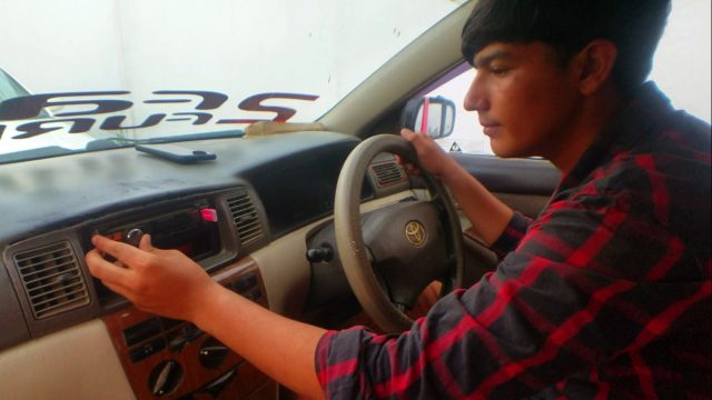
Drinking water from a mug or bottle. Adjusting the Radio is one of the most common forms of distracted driving. At any given time, more than 600,000 drivers are manipulating electronic devices, like radios, while driving.
Driving distractions are divided into three categories:
- Visual, which takes your eyes off the road?
- Cognitive, which takes your mind off the road, and
- Manual, which takes your hands off the steering wheel?
Listening to the radio or adjusting the station covers all three categories of distractions.
The National Highway Traffic Safety Administration estimates that drowsy driving was responsible for 72000 crashes, 44000 injuries, and 800 deaths in 2013 as reported in the United States of America. However, these numbers are underestimated and up to 6,000 fatal crashes each year may be caused by drowsy drivers.
In this tutorial, you will learn how to reduce distracted driving accidents using only Arduino, MPU6050 and a buzzer. If a driver writes a message and looks down for more than 2 seconds the buzzer is activated. So, if the driver looks down or looks up for more than 2 seconds a buzzer is activated which alerts the driver. This project can also be used as the driver drowsiness detection system. This is just a prototype model which can be further improved by designing a PCB. For the practical demonstration watch video tutorial given at the end.
If you don’t know about the MPU6050 module then watch the video which explains the extreme basics and if you want to display the mpu6050 data on 16×2 i2c LCD and ssd1306 OLED display then check out this article.
Amazon Links:
Arduino Nano USB-C Type (Recommended)
Other Tools and Components:
ESP32 WiFi + Bluetooth Module (Recommended)
Super Starter kit for Beginners
PCB small portable drill machines
DISCLAIMER:
Please Note: these are affiliate links. I may make a commission if you buy the components through these links. I would appreciate your support in this way!
Circuit Diagram of the Distracted Driving Accidents Project:
This schematic is designed in Cadsoft eagle 9.1.0 version. if you want to learn how to make a schematic and PCB then watch my tutorial.
The circuit diagram is very simple, as you can see VCC is connected with 3.3 volts, GND is connected with the GND, SCL and SDA are connected with the Arduino’s Analog pins A5 and A4, while the INT pin of the MPU6050 module is connected with pin number 2 of the Arduino.
The 5v Buzzer Positive leg is connected with the Arduino’s 5 volts. The ground leg of the buzzer is connected with the Collector of the 2n2222 NPN transistor while the emitter is connected with the Ground. The base of the 2n2222 NPN transistor is connected with the Arduino’s pin number 13 through a 10k resistor. So that’s all about the circuit diagram.
MPU6050 and Buzzer Interfacing with Arduino:
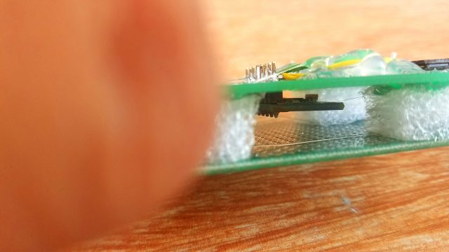
The MPU6050 module soldering is already explained in my previous tutorial, as you can see the MPU6050 module is sandwiched between the two Vero boards. This arrangement really helped me to easily calibrate the MPU6050 module. The MPU6050 interfacing with the Arduino is exactly the same as explained in the circuit diagram and in my previous tutorial on the MPU6050 module.
This time I added only a 5v buzzer, a 2n2222 NPN transistor, and a 10k resistor. As you can see the positive leg of the buzzer is connected with the Arduino’s 5 volts, the emitter is connected with the ground while the base is connected with the Arduino’s pin number 13.
After performing my initial testing, then I replaced the short jumper wires with longer wires, the soldering is explained in the video tutorial given at the end of this article. Finally, I fixed the MPU6050 module on the cap. The overall size of the project can be further reduced by designing our own PCB board for the ATmega328 microcontroller.
Distracted Driving Accidents MPU6050 Arduino Programming:
|
1 2 3 4 5 6 7 8 9 10 11 12 13 14 15 16 17 18 19 20 21 22 23 24 25 26 27 28 29 30 31 32 33 34 35 36 37 38 39 40 41 42 43 44 45 46 47 48 49 50 51 52 53 54 55 56 57 58 59 60 61 62 63 64 65 66 67 68 69 70 71 72 73 74 75 76 77 78 79 80 81 82 83 84 85 86 87 88 89 90 91 92 93 94 95 96 97 98 99 100 |
/* vcc = 3.3v Gnd = gnd int = 2 scl = a5 sda = a4 */ #include "I2Cdev.h" #include "MPU6050.h" int buzzer = 13; MPU6050 mpu; int16_t ax, ay, az; int16_t gx, gy, gz; int val; int prevVal; int valax; int valay; int valaz; // Tracks the time since last event fired unsigned long previousMillis=0; unsigned long int previoussecs = 0; unsigned long int currentsecs = 0; unsigned long currentMillis = 0; int secs = 0; int interval= 1 ; // updated every 1 second void setup() { Wire.begin(); Serial.begin(38400); Serial.println("Initialize MPU"); mpu.initialize(); Serial.println(mpu.testConnection() ? "Connected" : "Connection failed"); pinMode(buzzer, OUTPUT); } void loop() { currentMillis = millis(); currentsecs = currentMillis / 1000; if ((unsigned long)(currentsecs - previoussecs) >= interval) { secs = secs + 1; previoussecs = currentsecs; if (secs >= 59) { secs = 0; } // Serial.println("Seconds:"); // Serial.println(secs); } mpu.getMotion6(&ax, &ay, &az, &gx, &gy, &gz); valax = map(ax, -17000, 17000, 0, 255) ; valay = map(ay, -17000, 17000, 0, 255); valaz = map(az, -17000, 17000, 0, 255); Serial.println("ax: "); Serial.println(valax); //Serial.println("ay:"); //Serial.println(valay); //Serial.println("az: "); //Serial.println(valaz); //Serial.println(""); //Serial.println(""); delay(200); if ( (valax > 130) && (secs > 2) ) { digitalWrite(buzzer, HIGH); } if ( (valax >= 60) && (valax <= 100) ) { digitalWrite(buzzer, LOW); secs = 0; } if ( (valax < 50) && (secs > 2) ) { digitalWrite(buzzer, HIGH); } } |
How to reduce the Distracted Driving Accidents Program Explanation:
/*
vcc = 3.3v
Gnd = gnd
int = 2
scl = a5
sda = a4
*/
The MPU6050 GY-521 module can be powered up using 3.3 to 5 Volts. The INT pin is connected with the Arduino’s Pin number 2; the SCL Pin is connected with the Analog Pin A5 while the SDA Pin is connected with the Analog Pin A4 of the Arduino.
Before you start the programming, first of all, make sure that you download these Libraries. These libraries are available on my Website, you can find the library download links in my previous tutorial on the MPU6050.
#include “I2Cdev.h”
#include “MPU6050.h”
This is the same program which I used in my previous tutorials, this time I made a few changes.
I defined a pin for the Buzzer. as you can see the buzzer is connected with pin number 13 of the Arduino.
int buzzer = 13;
MPU6050 mpu;
int16_t ax, ay, az;
int16_t gx, gy, gz;
int val;
int prevVal;
int valax;
int valay;
int valaz;
To keep track of the time I defined some variables.
// Tracks the time since last event fired
unsigned long previousMillis=0;
unsigned long int previoussecs = 0;
unsigned long int currentsecs = 0;
unsigned long currentMillis = 0;
For the seconds counting I defined a variable of the type integer.
int secs = 0;
int interval= 1 ; // updated every 1 second
The value is updated every 1 second; this number can be adjusted as per your requirement. For this project 1 second works just perfect.
The void setup function consists of the same functions, this time I added only this line, which sets the buzzer as the output device.
void setup()
{
Wire.begin();
Serial.begin(38400);
Serial.println(“Initialize MPU”);
mpu.initialize();
Serial.println(mpu.testConnection() ? “Connected” : “Connection failed”);
pinMode(buzzer, OUTPUT);
}
void loop()
{
currentMillis = millis();
currentsecs = currentMillis / 1000;
if ((unsigned long)(currentsecs – previoussecs) >= interval)
{
secs = secs + 1;
previoussecs = currentsecs;
if (secs >= 59)
{
secs = 0;
}
// Serial.println(“Seconds:”);
// Serial.println(secs);
}
The above instructions are used for counting the seconds.
mpu.getMotion6(&ax, &ay, &az, &gx, &gy, &gz);
valax = map(ax, -17000, 17000, 0, 255) ;
valay = map(ay, -17000, 17000, 0, 255);
valaz = map(az, -17000, 17000, 0, 255);
Serial.println(“ax: “);
Serial.println(valax);
//Serial.println(“ay:”);
//Serial.println(valay);
//Serial.println(“az: “);
//Serial.println(valaz);
//Serial.println(“”);
//Serial.println(“”);
delay(200);
The following conditions are used to check if the driver is looking down, straight or up.
if ( (valax > 130) && (secs > 2) )
{
digitalWrite(buzzer, HIGH);
}
This condition means if the driver is looking down, maybe the person is typing a text message or adjust the radio etc for more than 2 seconds the buzzer will turn ON. This buzzer will remain ON until the driver looks straight.
if ( (valax >= 60) && (valax <= 100) )
{
digitalWrite(buzzer, LOW);
secs = 0;
}
This condition makes sure that the driver is looking straight and maintains the normal position.
if ( (valax < 50) && (secs > 2) )
{
digitalWrite(buzzer, HIGH);
}
While this condition means if the driver is looking up for more than 2 seconds, or maybe the driver is drinking water or a cold drink the buzzer will turn ON. The buzzer will only turn OFF when the driver gets back to its normal state.
}
For the practical demonstration watch the following video. If you have any question let me know in a comment. With this, the project “how to reduce the distracted driving accidents” comes to an end.


