Arduino Vs PLC, Technical Specs, Pinout, and Programming Examples
Table of Contents
Description:
Arduino Vs PLC- Hello and welcome back to Electronic clinic. In this article, we are going to take a look at the similarities and differences between Arduino and PLC. As you guys know I have been using the Fatek PLC FBS-14 in different projects as this version of the PLC is ideal for beginners, because it’s cheap. All the PLCs shares the same functionalities, the only difference can be in the prices, inputs and outputs, etc. So, I will do the comparison between the Arduino and Fatek PLC FBS-14. Unlike the PLC, Arduino is also the most powerful controller board, you can even build your own PLC using Arduino. In the end I will share with you the “PLC Arduino ARDBOX” this is a PLC developed using the Arduino board. We will talk about the PLC Arduino ARDBOX in detail. But for now, let’s concentrate on the Arduino Vs PLC. Without any further delay, let’s get started!!!
Amazon Links:
Arduino Nano USB-C Type (Recommended)
Fatek PLC, FBs-14MAR2-AC (FBs-14MA):
Other Tools and Components:
ESP32 WiFi + Bluetooth Module (Recommended)
Super Starter kit for Beginners
PCB small portable drill machines
*Please Note: These are affiliate links. I may make a commission if you buy the components through these links. I would appreciate your support in this way!
Arduino Vs PLC:
Arduino is an open-source electronic platform; this hardware allows anyone to complete automated electronic projects at low cost and in very little time making the Arduino ideal for prototyping. on the other hand, a PLC or programmable logic controller is an industrial computer that has been reinforced and adapted to control manufacturing processes. Let’s begin this comparison, let’s first take a look at some of the similarities between the Arduino and PLC.
Similarities between Arduino and PLC:
both are programmable both can continuously monitor the status of input signals and make decisions based on a custom program to change the status of devices connected to the output, so both can be used in automation. the language used to program an Arduino is basically a set of C and C++ functions on the other hand a PLC can use five different languages, the five programming languages are ladder diagram, function block diagram, structure text, instruction list, and sequential function chart.
languages use in PLC:
PLC Ladder diagram
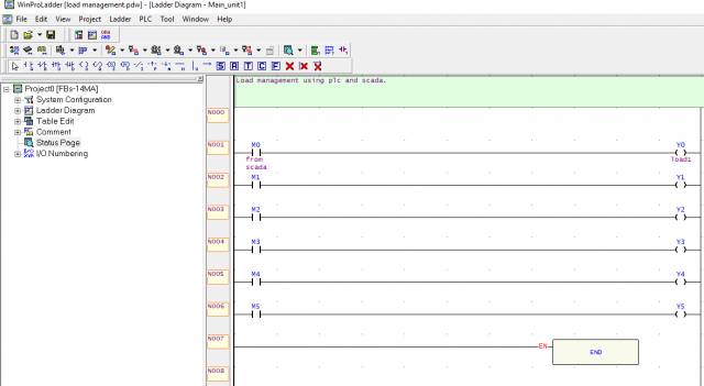
The purpose of this ladder logic program is to control the outputs Y0, Y1, …, y5 when the coil contacts M0, M1, …, M5 are activated. It’s very simple. If you write the same program for the Arduino it will take a lot of time and you will need to write multiple lines of code.
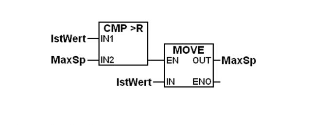
Function block diagram
Structure text
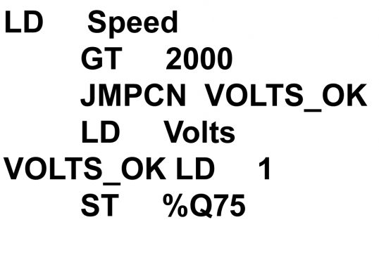
Instruction list
Sequential function chart
Arduino Programming:
|
1 2 3 4 5 6 7 8 9 10 11 12 13 14 15 |
int LED = 13; void setup() { // put your setup code here, to run once: Serial.begin(9600); pinMode(LED, OUTPUT); digitalWrite(LED, LOW); } void loop() { // put your main code here, to run repeatedly: digitalWrite(LED, HIGH); delay(1000); // 1 second delay digitalWrite(LED, LOW); delay(1000); } |
Just look at the Arduino code, the purpose of this code is to turn ON and turn OFF an LED at a regular interval of 1 second. The same thing can be done in PLC in only 1 line or maximum 2 lines using the LADDER Logic Programming. For the best understanding checkout my PLC and Arduino based projects.
Languages advantages between Arduino and PLC:
So in languages, the advantages for the PLCs with most PLCs, we can update the program in a short period of time. on the other hand, if there is a problem there are a variety of options in the system that we can configure like real time tables, real-time charts, real-time ladder logic view, etc, but help us to monitor all the variables in the i/o, all of these options facilitate the troubleshooting process the ladder logic and other languages, that the plc has made it very intuitive to make a change to the Arduino. It takes more time especially if there is a new person working with the system. It is more difficult to figure out C, and C++ instructions to display the data collected from the Arduino IO. We could use an external screen however troubleshooting the system, with the Arduino is more difficult. Here the advantage is also for the PLC; on the PLCs, I/O modules can be added and removed as needed. If any of the idle modules breaks that module is simply replaced, on the other hand, the I/O is embedded in the Arduino board if the I/O section of the Arduino is broken, we have to replace the entire board IO adaptability, and flexibility winner the PLC. When it comes to price the Arduino board and all components are cheaper than PLCs. The PLC’s are certified to work and perform under industrial conditions where there are high temperatures, noise, vibrations, and gas emissions etc. PLC’s have a robust designed to work in industrial environments.
About Fatek Fatek PLC FBS-14:
Above is the picture of the Fatek PLC FBS-14. This version of the Fatek PLCs series is best for the beginners. 14 mean that this PLC has 8 inputs and 6 outputs, 8 + 6 = 14.
The FATEK FB S Series PLC is a new generation of micro PLC equipped with excellent functions comparable to medium or large PLC, with up to five communication ports. The maximum I/O numbers are 256 points for Digital Input (DI) and Digital Output (DO), 64 words for Numeric Input (NI) and Numeric Output (NO). The Main Units of FBS are available in three types: MA (Economy Type), MC (High-Performance Type), and MN (High-Speed NC Type). With the combination of I/O point ranges from 10 to 60, a total of 17 models are available. Fourteen DI/DO and 12 NI/NO models are available for Expansion Units/Modules.
Specifications
FBs-14MCR2-AC:
8 points 24VDC digital input (up to 10KHz in 4 points)
6 Points Relay digital output
1 built-in RS-232 (can be expanded up to 3)
100~240VAC power supply,
I/O is not expandable
UL certified.
Notes for other ordering options/models:
FBs-(nn)MA(o)2-(p)
=== (nn) Digital I/O points ===
10 – 6 DI, 4 DO
14 – 8 DI, 6 DO
20 – 12 DI, 8 DO
24 – 14 DI, 10 DO
32 – 20 DI, 12 DO
40 – 24 DI, 16 DO
60 – 36 DI, 24 DO
=== (o) Digital Output Type ===
R – Relay output
T – Sink (NPN) output
J – Source (PNP) output²
=== (p) Power Supply ===
AC – 100~240VAC
D24 – 24 VDC²
D12 – 12 VDC²
About Arduino Uno:
Many boys and girls call Arduino as the microcontroller. Arduino is not a microcontroller but it is a controller board. Arduino is a family of different type of controller boards, including Arduino Uno, Arduino Nano, Arduino Mega, Arduino Micro, Arduino pro mini etc. Arduino Uno board is the most popular controller board in the Arduino Family and is used throughout the world. Arduino Uno board is the best choice for the beginners. The Arduino Uno is a microcontroller board based on the ATmega328. It has 14 digital input/output pins (of which 6 can be used as PWM outputs), 6 analog inputs, a 16 MHz crystal oscillator, a USB connection, a power jack, an ICSP header, and a reset button. It contains everything needed to support the microcontroller; simply connect it to a computer with a USB cable or power it with a AC-to-DC adapter or battery to get started. The Uno differs from all preceding boards in that it does not use the FTDI USB-to-serial driver chip. Instead, it features the Atmega8U2 programmed as a USB-to-serial converter. “Uno” means “One” in Italian and is named to mark the upcoming release of Arduino 1.0. The Uno and version 1.0 will be the reference versions of Arduino, moving forward. The Uno is the latest in a series of USB Arduino boards.
The ATmega328 has 32 KB (with 0.5 KB used for the boot loader). It also has 2 KB of SRAM and 1 KB of EEPROM (which can be read and written with the EEPROM library). Input and Output each of the 14 digital pins on the Uno can be used as an input or output, using pin Mode (), digital Write (), and digital Read () functions. They operate at 5 volts. Each pin can provide or receive a maximum of 40mA and has an internal pull-up resistor (disconnected by default) of 20-50 k Ohms.
Specifications
Microcontroller: ATmega328
Operating Voltage: V5
Input Voltage (recommended): 7-12V
Input Voltage (limits): 6-20V
Digital IO Pins: 4 (of which 6 provide PWM output)
Analog Input Pins: 6
DC Current per IO Pin: 40mA
DC Current for 3.3V Pin: 50mA
Flash Memory: 32 KB (ATmega328) of which 0.5 KB used by bootloader
SRAM: 2 KB
EEPROM: 1 KB
Clock Speed: 16 MHz
Package Including
1 x Compatible Arduino R3 Board
1 x USB OTG Cable
PLC Arduino ARDBOX
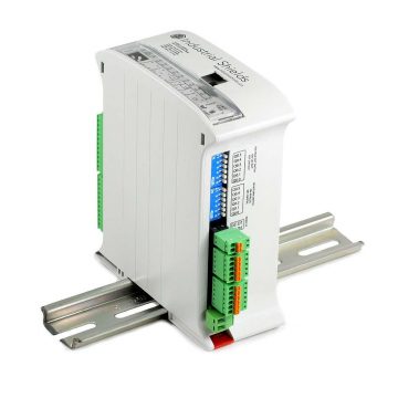
PLC Arduino ARDBOX is a product of Industrial Shields. There are so many other versions of the Industrial Arduino PLC, I highly recommend to visit the Industrial Shields official website and take a look at other amazing industrial products developed using Arduino, ESP32, and Rapsberry Pi.
Specifications for PLC Arduino ARDBOX 20 I/Os Analog HF Modbus
Main Technical Specs.
| Device | PLC |
| CPU | Arduino Leonardo |
| Uncategorized | |
| Choose your predefined Switch Configuration | Predefined Configuration not necessary (RS-485 as a default) or RS-232 |
| Inputs | |
| Inputs | 1-10 |
| Outputs | |
| Outputs | 1-10 |
| Communications | |
| I2C | Yes |
| SPI | Yes |
| Additional Communications | No Additional Communications or Wi-Fi & Bluetooth or GPRS or Lora or Dali |
| Additional functions | |
| µSD Card Socket | No |
Inputs:
| Total Inputs | 10 |
| Total Digital Optoisolated Inputs (5-24Vdc) | 2 |
| Digital Optoisolated Inputs (5-24Vdc) | 0 |
| Digital Optoisolated Inputs (5-24Vdc) | can work like interrupt Inputs INT (5-24Vdc) | 2 |
| 10 bit Analog Inputs (0-10V) | Digital (5-24Vdc) Inputs configurable by software | 8 |
Inputs notes – * From the (Xx) Digital, (Yx) can be configured as Analog (Xx = Total Digital In, Yx = Number of Analog In) * From the (Xx) Digital, (Zx) can be configured as Interrupt (Xx = Total Digital In, Zx = Number of Interrupt pins)
Outputs:
| Total Outputs | 10 |
| Digital Optoisolated Outputs (5-24Vdc) | 2 |
| Digital Optoisolated and PWM (5-24Vdc) | 8 bit Analog (0-10V) Outputs configurable by switch | 8 |
| Relay Outputs (220Vac – 5A) | 0 |
| Output notes |
Communications:
| Ethernet communication – NO |
| Wi-Fi & BLE (Bluetooth Low Energy) – NO |
| GPRS/GSM – NO |
| USB port (type B) communication (for uploading or debugging only) – 0 |
| Micro USB port (type B) communication (for uploading or debugging only) – 1 |
| I2C communication (interface with other Industrial Shields, sensors, I/Os modules) – 1 |
| Serial TTL (UART) communication – 0 |
| RS-232 communication – 1 |
| Half/Full Duplex RS-485 communication – 1 |
| SPI external port communication (using MOSI, MISO, SS pins of Arduino) – 1 |
| RTC (Real Time Clock. NOTE: I2C port used. See pinout modification) – NO |
| µSD Socket (using SPI port, chip select D53 pin) – NO |
Communications notes – * When using I2C, 2 inputs are lost
The Open Source Board CPU:
| Single Board Computer (SBC) Microcontroller | Arduino Leonardo Original Board (ATmega32u4) |
| Flash Memory (KB) | 32 |
| Flash Memory of which used by bootloader (KB) | 4 |
| SRAM (KB) | 2,5 |
| EEPROM (KB) | 1 |
| Clock Speed (MHz) | 16 |
Safety:
| Conformity with Health, Safety, and Environmental Protection (CE)
EN61010-1 | EN61010-2-201 | EN61131-2:2007(Clause 8: Zone A/B EMC and clause 11:LVD) | EN61000-6-4:2007 + A1 2011 (Emissions) | EN 61000-6-2:2005 (Immunity) |
| Medical Devices Directive (CE): 93/42/EEC |
| FCC Federal Code of Regulation (CFR) for Electronic Equipment: EMC: FCC Part 15 |
| RoHS: Directive 2002/95/EC | Restriction of Hazardous Substances (EEE) |
| UL: STD 61010-2-201 and UL STD 61010-1 | expecting final auditory (tested) |
| NCAGE (Commercial and Government Entity Code – Department of Defense): NCAGE 99SGB |Commercial and Government Entity Code | Boot&Work Corp SL Industrial Shields |
Other Information:
| PLC measures: 100x45x115 |
| DIN Rail mounting |
| Max. consum.: 1.5A |
| Power Supply Voltage (Vdc) Range: 12-24 |
| Power Consumption (VAC max.): 30 |
| Operating Temperture C: 0C-60C |
| Operating Temperature F: 32F-140F |
| Operating Relative Humidity % (no condensation): 10%-90% |
| Package Size: 13cm x 14cm x 8cm |
| Packaging: Box |
| ECCN Number: EAR99H |
| HTS Code: 8537.10.10.90 |
| 740.17 Language – 740.17 (b)(1) for self-classification or (b)(3) CCATS issued: §740.17 (b)(1) |
| Country of Origin: Spain |
| STATIC Sensitive: N |
| Moisture Sensitivity Level (MSL): MSL 1 – Unlimited |
| Lead Free |
| RoHS Compliant by Exemption? NO |
| Does Part Contain Lithium? N |
| Product Weight: 321 gram |
| Buy online or through our distributors (see the menu). We ship using DHL. You will receive your goods in 24-72 (Europe), 3-5 days for rest of the World. |
Other Technical Specifications: *Rx,Tx pins are not available using RS485. For SPI you need to choose another pin for Select Function (You can choose, SDA, SCL, Rx, Tx, Pins of Arduino)
How to Start with PLC Arduino ARDBOX
| 1. Download the open-source software “Arduino IDE” version 1.8.0 or higher and open it. |
| 2. Click on “File” and then on “Preferences“. |
| 3. See the “Additional Boards Manager URLs:” text box inside the “Settings” tab and add this URL: http://apps.industrialshields.com/main/arduino/boards/package_industrialshields_index.json |
| 4. Close the preferences window with the “Ok” button. |
| 5. Click on “Tools” menu , and open the “Boards” submenu, and click the “Boards Manager” option, to open the Boards Manager window. |
| 6. Search “industrialshields” to the search filter and select to the list and click “Install” or “Update” if you have not got the latest version. |
| 7. Close the “Boards Manager“. Now you can select each of our PLCs by clicking on “Tools“, then “Board“, then “Industrial Shields Boards” and select your family of PLCs. Contact support@industrialshields.com if you have any questions.” |
Check Out:
PLC based Projects


