Automatic Room Light Controller with bidirectional Visitor Counter using PLC
Table of Contents
Description:
Automatic Room Light Controller with Bidirectional Visitor Counter using PLC- Automatic Room Light Controller is a kind of project that every electronics student or professional wishes to make. If you search on Google you will find that there are so many articles and videos on how to make an Automatic Room Light Controller using the Arduino Uno “Atmega328” or any other microcontroller. As you know the Automatic Room Light Controller with Bidirectional Visitors counter is already done using the microcontrollers. So, I am not going to use the Arduino Uno or the 8051 family microcontrollers or the PIC microcontroller. I am going to make an advanced level Automatic Room Light Controller with a Bidirectional Visitor counter using the PLC.
In this article, you will learn how to use IR adjustable infrared Proximity Sensor 2v to 24V NPN type with the Fatek PLC and build an amazing Automatic Room Light Controller. I will explain the extreme basics, including the logic development using a 3d model, Circuit Diagram Explanation and Ladder Logic Diagram explanation.
In this project, a total of 4 infrared sensors will be used for the bidirectional visitor counting. The room light will turn ON if there is at least one person in the room. I have tested this project so many times and it has no errors, you can watch the practical demonstration in a video given at the end of this article. This project can be easily modified and any other load can be controlled. If you are new to the PLC programming, I will recommend first read my previous articles in which I have explained all the basics including the WinProLadder software download and how to use it, basics gates, timers,and counters, etc.
Without any further delay let’s get started!!!
Amazon Purchase Links:
Fatek PLC, FBs-14MAR2-AC (FBs-14MA):
IR adjustable infrared Proximity Sensor 2v to 24V:
Other Tools and Components:
Super Starter kit for Beginners
PCB small portable drill machines
*Please Note: These are affiliate links. I may make a commission if you buy the components through these links. I would appreciate your support in this way!
Logic Development:
Before you actually start working on a project, if it’s a hardware-based project or a software-based project, sit and think for some time, try to understand the basic working of the project, develop a logic how the programming will be done, etc. I myself started off by making a very basic 3d model which I designed in SolidWorks 2016.
Let’s suppose we have a room, and this room has only one door. So the same door will be used as the entrance and exit. So at this point, one thing is clear, that first, we will have to find the direction whether the person is entering into the room or leaving the room. So it means we will need two sensors for this.
This is a door frame, and currently, it has two sensors, one sensor is connected with X0 and the other one is connected with X1 input of the Fatek PLC.
Now let’s discuss different situations.
For example, I am that person, and right now I am entering into the room, so first of all, the sensor connected with X0 will be activated and then the sensor connected with X1 will be activated and a value in the register will be incremented; and similarly if I am leaving the room first of all the sensor connected with X1 will be activated and then the sensor connected with X0 will be activated and a value in the register will be decremented. so far, everything is just fine it’s incrementing and decrementing the values. So, this system will work fine, if I directly enter into the room or leave the room.
Now let’s discuss another situation.
For example, I am entering into the room and the sensor connected with x0 is activated and then I stand there for a while and decide not to enter and go back. Now what will happen the sensor was already activated, if during this time another person decided to leave the room, while he/she will be leaving the room the sensor X1 will be activated, at this point the system will behave in an abnormal way, instead of decrementing the value it will increment the value.
You know why?
Because sensor connected with X0 was already activated and then after that, the sensor connected with X1 was activated which is the same as if someone is entering into the room. So, instead of decrementing the value, it incremented the value.
So, this is a serious problem and we have to fix this. The same thing applies to the person leaving the room.
This problem can be solved by using two more infrared sensors. These two sensors will be used for resetting.
Let’s discuss how these reset sensors will help us solve this problem. for example I am entering into the room, so first of all the reset sensor will be activated, as soon as it is activated it will reset all the coils, then after that, sensor connected with x0 will be activated, now at this point if I enter into the room it will increment the value in register, and if decide to go back then during this time the reset sensor will be activated, which will reset all the coils. So, the same thing applies to the person leaving the room. So that’s it. Now we have to convert this logic into programming. Using this logic we can make an amazing automatic room light controller with a bidirectional visitor counter.
Circuit Diagram of the Automatic Room Light Controller with Bidirectional visitor counter using PLC:
The circuit diagram is very simple. 4 infrared sensors are connected with the Fatek PLC inputs X0, X1, X2, and X3. If you don’t know about the IR sensors you can visit my YouTube Channel Electronic Clinic, where you can find a complete playlist on PLC Tutorials. A relay is connected with the output Y3 which is used to turn ON and turn OFF the light Bulb or any other load connected. Now let’s discuss the Ladder Logic Programming.
Automatic Room Light Controller with visitor counter PLC Ladder Logic Programming:
You might find this program a bit complex and confusing but trust me this is very simple if you know about the basics. You can read my previous articles.
First of all, I started off with two inputs X0 and X1. With the help of these two sensors, we can know exactly whether the person is entering into the room or leaving the room. If the person is entering into the room the coil M0 will be set and also turns on the Y0 which is used as the indicator.
If the person is leaving the room then the coil M1 will be set and the output Y1 will turn ON which is also used as the indicator. Y0 and Y1 are just the indicators that show whether a person is entering or leaving the room.
M0 and M1 are used to detect if the person is entering or leaving the room. So if in case the person is leaving the room the M0 will be set high and it will remain high until we reset the M0 coil. The M3 coil will only be set high if M2 is high, M1 is high, Y1 is high and Y0 is low. You know very well if the person has passed the Sensor 0 then Y0 will be off and Y1 will be turned ON as the person is now in front of Sensor1. So this means that the person has passed both the sensors. Similarly, for the person leaving the room.
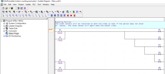
This portion of the Ladder Logic diagram makes sure to reset the coils if the person does not enter into the room or does not leave the room. R inside the parenthesis means to Reset the coil.
Now, this portion of the Ladder logic diagram makes sense. If the M2, M3, and M4 coils are set ”high” then high M23 for one cycle and then increment the value in R1 register; and similarly if the person is leaving the room then decrement the R1 register. If you don’t know about how to create a register table then read my previous article on Timers and Counters.
When the sensor connected with the X2 input of the Fatek PLC is activated the value stored in the R1 register is moved to R10.
Finally, we do the comparison and check if there is anyone in the room and control the room light accordingly. The Alarm can be used as the security, which you can figure out by yourself if you know how this works tell me in the comment.
This ladder logic program can be used in industries for counting objects. This is a bidirectional counter and can be used anywhere you want. This bidirectional visitor counter can also be used as your final year engineering project.
So, that’s all about the Automatic Room Light Controller with Bidirectional Visitor Counter using PLC for the practical demonstration watch video given below. So for the bad video quality, actually I recorded this video a long time ago. Don’t forget to subscribe to my Website and YouTube channel.
Watch Video Tutorial:


sir excellent project. May i request you to send the same project code with four sensors in arduino .