PLC HMI based on the Arduino Mega & 5 inch TFT touchscreen
Table of Contents
Description:
PLC HMI based on the Arduino Mega & TFT touchscreen- In this project, we are going to control the Fatek PLC 14-FBS using Arduino Mega, and a 5 inch TFT touch screen. We will be designing our own GUI “Graphical User Interface” application for the 5 inch TFT Touch Screen. The control signals to the PLC will be given through this GUI application consisting of 6 buttons. Using this GUI application 6 loads can be controlled connected with the outputs of Fatek PLC.
In this tutorial, you will also learn how to use Arduino Mega and PLC together. The control signals from the Arduino Mega are transferred to the PLC inputs through SPDT type relays. This is not an industrial level project, because this is not the actual PLC HMI system. But, this project can help you to learn how to make a GUI application and then how to use this application to control a PLC. This project will also help you understand, how relays are connected with the PLC inputs and outputs. This is an ideal project for electrical and electronics engineering students. This project can be used as the final year engineering project.
Without any further delay, let’s get started!!!
Amazon Purchase Links:
Fatek PLC, FBs-14MAR2-AC (FBs-14MA):
ITDB02 Arduino mega shield 2.1:
Other Tools and Components:
Super Starter kit for Beginners
PCB small portable drill machines
*Please Note: These are affiliate links. I may make a commission if you buy the components through these links. I would appreciate your support in this way!
PLC HMI System:
PLC HMI, PLC and HMI these are two different technologies combined together to make an advanced level industrial monitoring and control system. PLC stands for “Programmable Logic Controller” and HMI stands for “Human Machine Interface”.
PLC HMI system is used to monitor and control different industrial processes on a Touch Screen. An HMI is simply an Interface; HMI is a very broad term that can include industrial computers, office equipment, MP3 players and household appliances. PLC HMI systems are very famous as it provides a visual representation of a monitoring and control system. The HMI system eliminates the need for a computer-based SCADA system. You can use the HMI touch screen to control anything you want.
The terms like Automation, HMI, PLC, and SCADA are not new; a tremendous amount of work has already been done on these different technologies, each one has its own advantages and disadvantages. For example,
If we use a computer-based SCADA monitoring and control system then we will need a computer or laptop. This way the PLC can be controlled from a supervisory control room, it is easy to operate and the PLC SCADA application programming can be easily modified. Computer-based PLC control and monitoring system have only one disadvantage that is it cannot be used with the machine on site.
The PLC HMI systems are a bit expensive and the programming is a bit complex, but its major advantage is that it can be fixed on the machines. This way the entire machine can be monitored and controlled using the PLC HMI touchscreen. It eliminates the use of long cables and wired buttons.
HMI (Human Machine Interface) is exactly what the name implies; a graphical user interface that allows humans and machines to interact. As I said earlier, in this project, I am not going to make an advanced level PLC HMI control system the ones used in industries, but I will be teaching you how to design a very basic GUI application for the TFT touch screen which can be used with the Arduino Mega to control a PLC.
Types of HMI Systems:
There are mainly three basic types of HMIs.
- The Pushbutton replacer
- The Data Handler and
- The Overseer.
Long before the invention of HMI technology, the PLC control system might consist of hundreds of pushbuttons for controlling different processes. The HMI pushbutton replacer streamlined manufacturing processes, centralizing all the functions of each button into one location. In this project, I will be focusing on the pushbutton or permanent button replacer, which makes this control system purely digital. There will be no serial communication between the Arduino Mega and PLC but I will be using relays for the control signals.
SOFTWARES used in this Project:
- WinProLadder for PLC programming.
- C programming for touch screen HMI, GUI application designing.
- Cadsoft eagle for Schematics and PCBs designing.
- Proteus for simulation.
5 inch TFT touch screen:
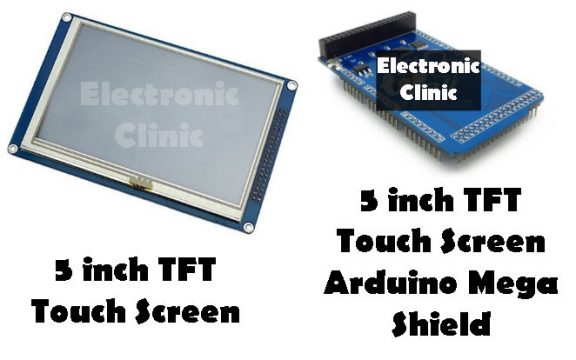
The 5 inch TFT Touch Screen 800×480 comes with a mega shield which perfectly sets on the Arduino Mega.
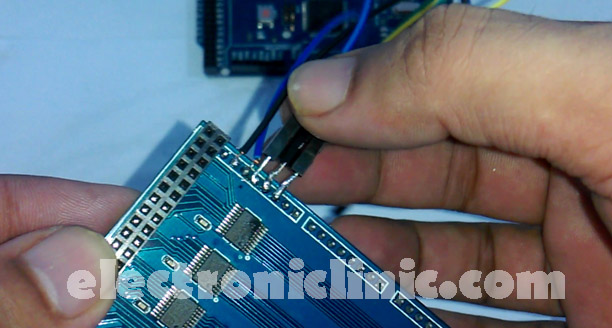
This shield is not provided with the female headers due to which it cannot be connected with other electronic devices.
But we can solder connection wires which can be then connected with other electronic components; in my case, I will connect these wires with the Relays.
I soldered jumper wires with the Mega pins 13, 12, 11, and 10. If you want you can solder more wires as per your requirements.
This 5 inch TFT shield sets perfectly on the Arduino Mega2560 occupying all the pins, so that’s why I soldered these jumper wires with the TFT shield.
Now we are done with the 5 inch TFT touch screen shield and it can be used with the Touch screen. The wires soldered can be used to control the relays.
Now let’s have a look at the complete circuit diagram. For the easy understanding, I have separated the Arduino Mega3560 side from the PLC.
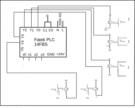
PLC side Circuit Diagram:
12v relays are connected with the PLC outputs Y0, Y1, Y2, Y3, and Y4. As I am going to control electrical loads using 12v relays so that’s why I connected C0 and C1 with 12v. One side of the relay coils are connected with the GND, while the other sides are connected with the PLC outputs Y0…Y4. The PLC inputs X0 to XN will be connected with the Mega2560 relay module.
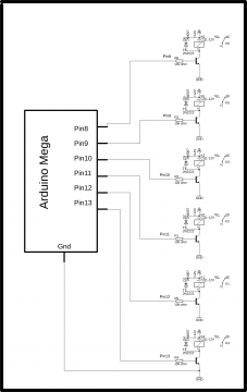
Mega2560 side Circuit Diagram:
As you can see 6 relays are connected with the Arduino Mega2560. The number of relays can be increased or decreased as per the requirement.
Relays can be controlled through a low voltage signal and can be used to control high power circuit with a lower power circuit. To make a relay Operate, first of all, we will have to energize the relay coil by simply passing the current through the relay coil. Most of the relays which are available in the market are 12v and 24v. I will be using 12v relays. 12v relay cannot be directly controlled by the controller, that’s why electromechanical relays need a driver circuit. A driver circuit simply consists of an NPN or PNP type transistor and a resistor. It depends on the designer whether he/she wants to use the PNP or NPN type transistor. I will be using a NPN transistor. For the Driver circuit to design, first of all we find the relay coil resistance using a digital multimeter. The relay voltage is already known which is12v. Then by using the ohms law
V = IR
V = 12
R= 375 ohms ( we checked the resistance of the relay coil using a digital multimeter)
I =?
I = V / R
I = .032 amps
I = 32 milliamps
After finding the relay coil current then select any general-purpose NPN type transistor who’s collector current is greater than the relay coil current. In my case, I will use a 2n2222 NPN transistor because it is cheap, easily available in the market and moreover it can handle more current than the calculated value which was 32ma.
A 10k resistor is connected with the base of the 2n2222 NPN transistor as it’s a BJT bipolar junction transistor and it’s a current-controlled device so that’s why a 10k resistor must be added to limit the current.
Arduino Mega2560 and PLC together:
The Arduino Mega2560 is connected with the PLC inputs X0 to Xn through the relays discussed above. Follow the following steps.
- Connect +24v from the PLC with the common pins of all the relays which are connected with the Arduino Mega.
- Now connect the normally open legs of all the relays with the PLC inputs X0 to Xn.
Now, these relays can be used to give a 24v input signal to the PLC. These relays will be controlled through the 5 inch TFT HMI touch screen.
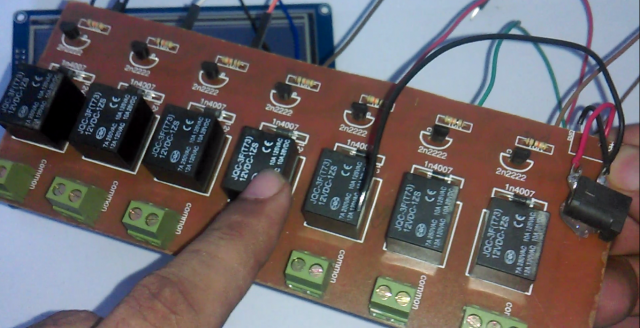
To make the interfacing simple I designed my own relay modules
Download PCB layout: relay module
Interfacing Arduino Mega HMI touch screen with PLC:
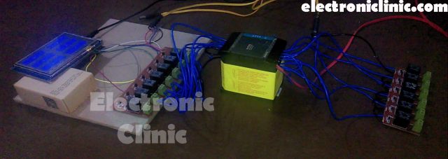
In the picture you can see, the Arduino Mega2560 and 5 inch TFT HMI touch screen is used to control the relays which are connected with the PLC inputs. Other relays are connected at the output side which is used to control the electrical loads.
If you have never used the 5 inch TFT touch screen then I highly recommend read my previous articles, in which I have explained all the basics. You can find links in the related projects section given at the end of this article.
Arduino Mega2560 5 inch TFT HMI touch screen Programming:
Before you start the programming, first of all, download the libraries used in this project. This is the same program that I have used in my previous tutorials; you can find links in the related projects section given at the end.
|
1 2 3 4 5 6 7 8 9 10 11 12 13 14 15 16 17 18 19 20 21 22 23 24 25 26 27 28 29 30 31 32 33 34 35 36 37 38 39 40 41 42 43 44 45 46 47 48 49 50 51 52 53 54 55 56 57 58 59 60 61 62 63 64 65 66 67 68 69 70 71 72 73 74 75 76 77 78 79 80 81 82 83 84 85 86 87 88 89 90 91 92 93 94 95 96 97 98 99 100 101 102 103 104 105 106 107 108 109 110 111 112 113 114 115 116 117 118 119 120 121 122 123 124 125 126 127 128 129 130 131 132 133 134 135 136 137 138 139 140 141 142 143 144 145 146 147 148 149 150 151 152 153 154 155 156 157 158 159 160 161 162 163 164 165 166 167 168 169 170 171 172 173 174 175 176 177 178 179 180 181 182 183 184 185 186 187 188 189 190 191 192 193 194 195 196 197 198 199 200 201 202 203 204 205 206 207 208 209 210 211 212 213 214 215 216 217 218 219 220 221 222 223 224 225 226 227 228 229 230 231 232 233 234 235 236 237 238 239 240 241 242 243 244 245 246 247 248 249 250 251 252 253 254 255 256 257 258 259 260 261 262 263 264 265 266 267 268 269 270 271 272 273 274 275 276 277 278 279 280 281 282 283 284 285 286 287 288 289 290 291 292 293 294 295 296 297 298 299 300 301 302 303 304 305 306 307 308 309 310 311 312 313 314 315 316 317 318 319 320 321 322 323 324 325 326 327 328 329 330 331 332 333 334 335 336 337 338 339 340 341 342 343 344 345 346 347 348 349 350 351 352 353 354 355 356 357 358 359 360 361 362 363 364 365 366 367 368 369 370 371 372 373 374 375 376 377 378 379 380 381 382 383 384 385 386 387 388 389 390 391 392 393 394 395 396 397 398 399 400 401 402 403 404 405 406 407 408 409 410 411 412 413 414 415 416 417 418 419 420 421 422 423 424 425 426 427 428 429 430 431 432 433 434 435 436 437 438 439 440 441 442 443 444 445 446 447 448 449 450 |
#include <UTouch.h> #include <UTouchCD.h> #define TOUCH_ORIENTATION LANDSCAPE #include <UTFT_Buttons.h> #include <UTFT.h> extern uint8_t SmallFont[]; extern uint8_t BigFont[]; extern uint8_t SevenSegNumFont[]; int button1on = 0; int button2on = 0; int button3on = 0; int button4on = 0; int button5on = 0; int button6on = 0; int device1 = 13; int device2 = 12; int device3 = 11; int device4 = 10; int device5 = 9; int device6 = 8; int x, y; char stCurrent[20]=""; int stCurrentLen=0; char stLast[20]=""; int bg[] = { 0, 0, 255}; int fg[] = { 255, 255, 255}; UTFT myGLCD(ITDB50, 38,39,40,41); // Remember to change the model parameter to suit your display module! UTouch myTouch(6,5,4,3,2); // for button1 int button1x1 = 10; // 90 int button1y1 = 20; // 180 int button1x2 = 350; // 220 int button1y2 = 130; // 230 // for button2 int button2x1 = 410; // 160 int button2y1 = 20; // 20 int button2x2 = 740; // 290 int button2y2 = 130; // 80 // for button3 int button3x1 = 10; // 310 int button3y1 = 170; // 20 int button3x2 = 350; // 450 int button3y2 = 280; // 80 // for button4 int button4x1 = 410; // 160 int button4y1 = 170; // 20 int button4x2 = 740; // 290 int button4y2 = 280; // 80 // for button5 int button5x1 = 10; // 310 int button5y1 = 320; // 20 int button5x2 = 350; // 450 int button5y2 = 430; // 80 // for button6 int button6x1 = 410; // 160 int button6y1 = 320; // 20 int button6x2 = 740; // 290 int button6y2 = 430; // 80 // Finally we set up UTFT_Buttons :) void drawButtons() { // Draw the upper row of buttons myGLCD.setColor(bg[0], bg[1], bg[2]); myGLCD.fillRoundRect (button1x1, button1y1, button1x2, button1y2); myGLCD.setColor(fg[0], fg[1], fg[2]); myGLCD.drawRoundRect (button1x1, button1y1, button1x2, button1y2); myGLCD.print(" ON", 140, 70); // 115, 195 myGLCD.setBackColor (0, 0, 255); // button2 codding myGLCD.setColor(bg[0], bg[1], bg[2]); myGLCD.fillRoundRect (button2x1, button2y1, button2x2, button2y2); myGLCD.setColor(fg[0], fg[1], fg[2]); myGLCD.drawRoundRect (button2x1, button2y1, button2x2, button2y2); myGLCD.print(" ON", 540, 70); // 115, 195 myGLCD.setBackColor (0, 0, 255); // button3 codding myGLCD.setColor(bg[0], bg[1], bg[2]); myGLCD.fillRoundRect (button3x1, button3y1, button3x2, button3y2); myGLCD.setColor(fg[0], fg[1], fg[2]); myGLCD.drawRoundRect (button3x1, button3y1, button3x2, button3y2); myGLCD.print(" ON", 140, 220); // 115, 195 myGLCD.setBackColor (0, 0, 255); // button4 codding myGLCD.setColor(bg[0], bg[1], bg[2]); myGLCD.fillRoundRect (button4x1, button4y1, button4x2, button4y2); myGLCD.setColor(fg[0], fg[1], fg[2]); myGLCD.drawRoundRect (button4x1, button4y1, button4x2, button4y2); myGLCD.print(" ON", 540, 220); // 115, 195 myGLCD.setBackColor (0, 0, 255); // button5 codding myGLCD.setColor(bg[0], bg[1], bg[2]); myGLCD.fillRoundRect (button5x1, button5y1, button5x2, button5y2); myGLCD.setColor(fg[0], fg[1], fg[2]); myGLCD.drawRoundRect (button5x1, button5y1, button5x2, button5y2); myGLCD.print(" ON", 140, 370); // 115, 195 myGLCD.setBackColor (0, 0, 255); // button6 codding myGLCD.setColor(bg[0], bg[1], bg[2]); myGLCD.fillRoundRect (button6x1, button6y1, button6x2, button6y2); myGLCD.setColor(fg[0], fg[1], fg[2]); myGLCD.drawRoundRect (button6x1, button6y1, button6x2, button6y2); myGLCD.print(" ON", 540, 370); // 115, 195 myGLCD.setBackColor (0, 0, 255); // write names myGLCD.setColor(fg[1], fg[3], fg[6]); myGLCD.setBackColor (0, 0, 0); myGLCD.print("Device1", 10, 135); myGLCD.print("Device2", 410, 135); myGLCD.print("Device3", 10, 285); myGLCD.print("Device4", 410, 285); myGLCD.print("Device5",10, 435); myGLCD.print("Device6", 410, 435); myGLCD.setColor(fg[1], fg[0], fg[6]); myGLCD.setBackColor (0, 1, 0); myGLCD.print("HMI PLC, COMSAT UNIVERSITY", 10, 462); /* myGLCD.setColor(fg[1], fg[3], fg[6]); myGLCD.setBackColor (0, 1, 0); // for line 1 myGLCD.drawRect(10, 152, 740, 155); // x1, y1, x2, y2 myGLCD.setColor(fg[0], fg[1], fg[2]); myGLCD.fillRect(10, 120, 610, 124); // for line 2 myGLCD.drawRect(10, 302, 740, 305); // x1, y1, x2, y2 myGLCD.setColor(fg[0], fg[1], fg[2]); myGLCD.fillRect(10, 120, 610, 124); // for line 3 myGLCD.drawRect(10, 452, 740, 453); // x1, y1, x2, y2 myGLCD.setColor(fg[0], fg[1], fg[2]); myGLCD.fillRect(10, 120, 610, 124); */ } void setup() { Serial.begin(9600); pinMode(device1, OUTPUT); pinMode(device2, OUTPUT); pinMode(device3, OUTPUT); pinMode(device4, OUTPUT); pinMode(device5, OUTPUT); pinMode(device6, OUTPUT); digitalWrite(device1, LOW); digitalWrite(device2, LOW); digitalWrite(device3, LOW); digitalWrite(device4, LOW); digitalWrite(device5, LOW); digitalWrite(device6, LOW); // Initial setup myGLCD.InitLCD(); myGLCD.clrScr(); myTouch.InitTouch(); myTouch.setPrecision(PREC_EXTREME); //PREC_MEDIUM , PREC_HI, PREC_EXTREME myGLCD.setFont(BigFont); myGLCD.setBackColor(0, 0, 255); drawButtons(); } void loop() { while (true) { if (myTouch.dataAvailable()) { myTouch.read(); x=myTouch.getX(); y=myTouch.getY(); // FOR BUTTON1 if ((x>=button1x1 && x<=button1x2 && y >=button1y1 && y<=button1y2)&&(button1on == 0) ) // Button: Enter { waitForIt(button1x1, button1y1, button1x2, button1y2); myGLCD.setColor(bg[0], bg[1], bg[2]); myGLCD.fillRoundRect (button1x1, button1y1, button1x2, button1y2); myGLCD.setColor(fg[0], fg[1], fg[2]); myGLCD.drawRoundRect (button1x1, button1y1, button1x2, button1y2); myGLCD.print(" OFF", 140, 70); myGLCD.setBackColor (0, 0, 255); Serial.println("ON"); digitalWrite(device1,HIGH); button1on = 1; x=0; y=0; delay(1000); } if ((x>=button1x1 && x<=button1x2 && y >=button1y1 && y<=button1y2)&&(button1on == 1) ) // Button: Enter { waitForIt(button1x1, button1y1, button1x2, button1y2); myGLCD.setColor(bg[0], bg[1], bg[2]); myGLCD.fillRoundRect (button1x1, button1y1, button1x2, button1y2); myGLCD.setColor(fg[0], fg[1], fg[2]); myGLCD.drawRoundRect (button1x1, button1y1, button1x2, button1y2); myGLCD.print(" ON", 140, 70); myGLCD.setBackColor (0, 0, 255); Serial.println("off"); digitalWrite(device1,LOW); button1on = 0; x=0; y=0; delay(1000); } // for button2 if ((x>=button2x1 && x<=button2x2 && y >=button2y1 && y<=button2y2)&&(button2on == 0) ) // Button: Enter { waitForIt(button2x1, button2y1, button2x2, button2y2); myGLCD.setColor(bg[0], bg[1], bg[2]); myGLCD.fillRoundRect (button2x1, button2y1, button2x2, button2y2); myGLCD.setColor(fg[0], fg[1], fg[2]); myGLCD.drawRoundRect (button2x1, button2y1, button2x2, button2y2); myGLCD.print(" OFF", 540, 70); myGLCD.setBackColor (0, 0, 255); Serial.println("ON"); digitalWrite(device2,HIGH); button2on = 1; x=0; y=0; delay(1000); } if ((x>=button2x1 && x<=button2x2 && y >=button2y1 && y<=button2y2)&&(button2on == 1) ) // Button: Enter { waitForIt(button2x1, button2y1, button2x2, button2y2); myGLCD.setColor(bg[0], bg[1], bg[2]); myGLCD.fillRoundRect (button2x1, button2y1, button2x2, button2y2); myGLCD.setColor(fg[0], fg[1], fg[2]); myGLCD.drawRoundRect (button2x1, button2y1, button2x2, button2y2); myGLCD.print(" ON", 540, 70); myGLCD.setBackColor (0, 0, 255); Serial.println("off"); digitalWrite(device2,LOW); button2on = 0; x=0; y=0; delay(1000); } // for button3 if ((x>=button3x1 && x<=button3x2 && y >=button3y1 && y<=button3y2)&&(button3on == 0) ) // Button: Enter { waitForIt(button3x1, button3y1, button3x2, button3y2); myGLCD.setColor(bg[0], bg[1], bg[2]); myGLCD.fillRoundRect (button3x1, button3y1, button3x2, button3y2); myGLCD.setColor(fg[0], fg[1], fg[2]); myGLCD.drawRoundRect (button3x1, button3y1, button3x2, button3y2); myGLCD.print(" OFF", 140, 220); myGLCD.setBackColor (0, 0, 255); Serial.println("ON"); digitalWrite(device3,HIGH); button3on = 1; x=0; y=0; delay(1000); } if ((x>=button3x1 && x<=button3x2 && y >=button3y1 && y<=button3y2)&&(button3on == 1) ) // Button: Enter { waitForIt(button3x1, button3y1, button3x2, button3y2); myGLCD.setColor(bg[0], bg[1], bg[2]); myGLCD.fillRoundRect (button3x1, button3y1, button3x2, button3y2); myGLCD.setColor(fg[0], fg[1], fg[2]); myGLCD.drawRoundRect (button3x1, button3y1, button3x2, button3y2); myGLCD.print(" ON", 140, 220); myGLCD.setBackColor (0, 0, 255); Serial.println("off"); digitalWrite(device3,LOW); button3on = 0; x=0; y=0; delay(1000); } // for button4 if ((x>=button4x1 && x<=button4x2 && y >=button4y1 && y<=button4y2)&&(button4on == 0) ) // Button: Enter { waitForIt(button4x1, button4y1, button4x2, button4y2); myGLCD.setColor(bg[0], bg[1], bg[2]); myGLCD.fillRoundRect (button4x1, button4y1, button4x2, button4y2); myGLCD.setColor(fg[0], fg[1], fg[2]); myGLCD.drawRoundRect (button4x1, button4y1, button4x2, button4y2); myGLCD.print(" OFF", 540, 220); myGLCD.setBackColor (0, 0, 255); Serial.println("ON"); digitalWrite(device4,HIGH); button4on = 1; x=0; y=0; delay(1000); } if ((x>=button4x1 && x<=button4x2 && y >=button4y1 && y<=button4y2)&&(button4on == 1) ) // Button: Enter { waitForIt(button4x1, button4y1, button4x2, button4y2); myGLCD.setColor(bg[0], bg[1], bg[2]); myGLCD.fillRoundRect (button4x1, button4y1, button4x2, button4y2); myGLCD.setColor(fg[0], fg[1], fg[2]); myGLCD.drawRoundRect (button4x1, button4y1, button4x2, button4y2); myGLCD.print(" ON", 540, 220); myGLCD.setBackColor (0, 0, 255); Serial.println("ON"); digitalWrite(device4,LOW); button4on = 0; x=0; y=0; delay(1000); } // for button5 if ((x>=button5x1 && x<=button5x2 && y >=button5y1 && y<=button5y2)&&(button5on == 0) ) // Button: Enter { waitForIt(button5x1, button5y1, button5x2, button5y2); myGLCD.setColor(bg[0], bg[1], bg[2]); myGLCD.fillRoundRect (button5x1, button5y1, button5x2, button5y2); myGLCD.setColor(fg[0], fg[1], fg[2]); myGLCD.drawRoundRect (button5x1, button5y1, button5x2, button5y2); myGLCD.print(" OFF", 140, 370); myGLCD.setBackColor (0, 0, 255); Serial.println("ON"); digitalWrite(device5,HIGH); button5on = 1; x=0; y=0; delay(1000); } if ((x>=button5x1 && x<=button5x2 && y >=button5y1 && y<=button5y2)&&(button5on == 1) ) // Button: Enter { waitForIt(button5x1, button5y1, button5x2, button5y2); myGLCD.setColor(bg[0], bg[1], bg[2]); myGLCD.fillRoundRect (button5x1, button5y1, button5x2, button5y2); myGLCD.setColor(fg[0], fg[1], fg[2]); myGLCD.drawRoundRect (button5x1, button5y1, button5x2, button5y2); myGLCD.print(" ON", 140, 370); myGLCD.setBackColor (0, 0, 255); Serial.println("ON"); digitalWrite(device5,LOW); button5on = 0; x=0; y=0; delay(1000); } // for button6 if ((x>=button6x1 && x<=button6x2 && y >=button6y1 && y<=button6y2)&&(button6on == 0) ) // Button: Enter { waitForIt(button6x1, button6y1, button6x2, button6y2); myGLCD.setColor(bg[0], bg[1], bg[2]); myGLCD.fillRoundRect (button6x1, button6y1, button6x2, button6y2); myGLCD.setColor(fg[0], fg[1], fg[2]); myGLCD.drawRoundRect (button6x1, button6y1, button6x2, button5y2); myGLCD.print(" OFF", 540, 370); myGLCD.setBackColor (0, 0, 255); Serial.println("ON"); digitalWrite(device6,HIGH); button6on = 1; x=0; y=0; delay(1000); } if ((x>=button6x1 && x<=button6x2 && y >=button6y1 && y<=button6y2)&&(button6on == 1) ) // Button: Enter { waitForIt(button6x1, button6y1, button6x2, button6y2); myGLCD.setColor(bg[0], bg[1], bg[2]); myGLCD.fillRoundRect (button6x1, button6y1, button6x2, button6y2); myGLCD.setColor(fg[0], fg[1], fg[2]); myGLCD.drawRoundRect (button6x1, button6y1, button6x2, button6y2); myGLCD.print(" ON", 540, 370); myGLCD.setBackColor (0, 0, 255); Serial.println("ON"); digitalWrite(device6,LOW); button6on = 0; x=0; y=0; delay(1000); } } } } void waitForIt(int x1, int y1, int x2, int y2) { myGLCD.setColor(255, 0, 0); myGLCD.drawRoundRect (x1, y1, x2, y2); while (myTouch.dataAvailable()){ } delay(20); // list all files in the card with date and size myGLCD.setColor(fg[0], fg[1], fg[2]); myGLCD.drawRoundRect (x1, y1, x2, y2); } |
PLC ladder logic diagram:
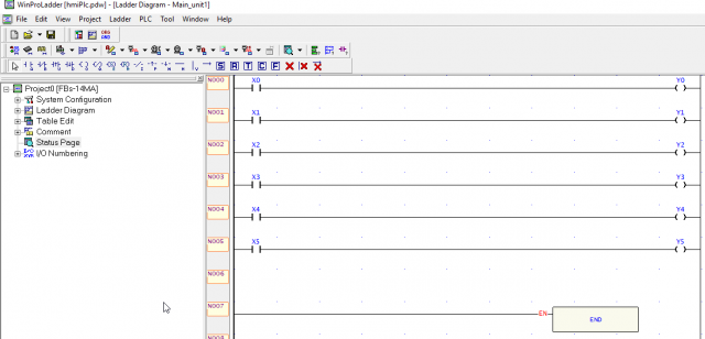
As you can see the Ladder Logic programming used in this project is very simple. This program is developed using WinProLadder software. If you don’t know how to use the WinProLadder software then read my previous articles, in which you will learn about the extreme basics, installation, how to use the software, basic gates, timers and counters, etc.
Video:
