DC DC Converter Complete Guide, DC DC Converter circuit Examples
Last Updated on August 16, 2024 by Engr. Shahzada Fahad
Table of Contents
DC DC Converter Introduction:
DC DC Converter Definition:
A DC-to-DC converter is an electronic circuit or electromechanical device that converts a source of direct current (DC) from one voltage level to another. It is a type of electric power converter. Power levels range from very low (small batteries) to very high (high-voltage power transmission).
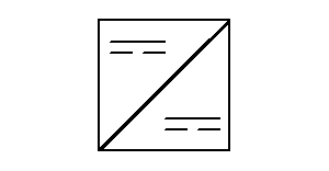
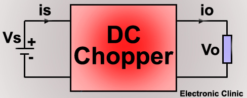
DC DC Converter Symbol:
Following is the symbol of DC to DC converter:
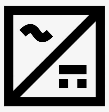
AC DC Converter Symbol:
Following is the symbol of AC to DC converter.
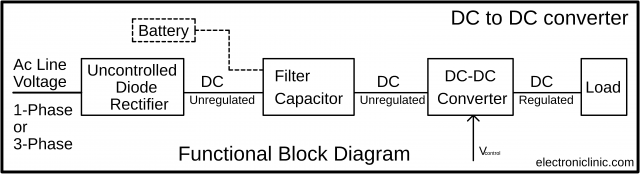
DC DC Converter Block Diagram
What does a DC DC Converter Do?
This is one of the most commonly asked questions.
Generally, DC-DC converters are electronic devices used whenever there is a need to bring up or down a DC-voltage level to another.
Or
DC/DC converters are used for the following reasons:
– To step down the voltage from a high voltage source to a lower voltage,
– To match the loads to the power supply,
– To isolate the primary and secondary circuits
Or
It is a type of converter that works very efficiently. It helps to change one level/voltage of DC into another level/voltage of DC.
You may, for example, have a solar power system to charge a battery of 12V battery but your Arduino processor and I2C or RS232 IC for communication monitoring of the solar power plant on a mobile telephone or 3G data link needs only 3.5V. Instead of using a resistor to consume the energy difference the DC/DC converter converts the one source to the other more efficiently.
Or
Usually, DC-DC Converters like Choppers or Buck-boost converters are used to extract DC Voltage from DC Voltage. It is useful in several instances…
1) By changing voltage levels-depending on duly cycle it is proportional to D or (1/ (1-D)).
2) Switching
3) Safety and match power requirements.
4) Domestic appliances or even in small machines.
5) Pulse Creation etc.
Or
DC to DC converters are chopper whose output voltage level could be higher or lower than its input voltage.
Or
Basically, a dc-dc converter is an electronic circuit that is used to step up (boost converter) or step down (Buck converter) the dc voltage to get the desired voltage.
DC DC converter topologies
DC to DC Converters can be divided into two categories:
- The isolated Converters and
- The non-isolated Converters
For isolated Converters, besides galvanic isolation, the transformers can be manipulated to obtain the required voltage at the output. The most famous of these topologies are the DAB or dual active bridge Converters. However, there are other important issues that might need to be considered besides efficiency.
The non-isolated converters have a large variation. But, mainly designed to obtain high efficiency, high gain, and high power density.
DC DC Converter Working:
I have been using DC power supplies in almost all of my projects. A DC power supply is used in most of the appliances where a constant voltage is required e.g a regulated power supply based on the LM7805 voltage regulator. DC stands for Direct Current, in which the current flow is unidirectional. The process of DC conversion can be done by DC Converters. The charge carriers in DC supply travel in a single direction. Solar cells, batteries, and thermocouples are the sources of DC supply. A DC voltage can produce a certain amount of constant electricity, which becomes weak when it travels further longer. An AC voltage from the generator can change their strength when they travel through a transformer.
As explained earlier, a DC to DC converter takes the voltage from a DC source and converts the voltage of supply into another DC voltage level “High or Low”. They are used to increase or decrease the voltage level. This is commonly used in automobiles, portable chargers, and portable DVD players. Some devices need a certain amount of voltage to run the device. Too much power can destroy the device or less power may not be able to run the device. The converter takes the power from the battery and cuts down the voltage level, similarly a converter step-up the voltage level. For example, it might be necessary to step down the power of a large battery of 24V to 12V to run a radio.
The converter takes the power from the battery and cuts down the voltage level, similarly a converter step-up the voltage level. For example, it might be necessary to step down the power of a large battery of 24V to 12V to run a radio.
The discussion we have done so far, it might be clear to you now, that the DC DC converters are used to change the output voltage as per the requirement. Different types of converts are used to step up or step down the voltage which we will discuss in detail.
DC DC converter applications:
Consider a desktop PC for an example. Inside the cabinet, you can see several sub-circuits, each with its own voltage level requirement different from that supplied by the battery or an external supply. So you need a variable dc, and obviously it should be small yet efficient. In fact, an SMPS(PSU) consists of a rectifier and dc-dc converter(along with many other components).
Wind energy like airheads is unreliable and inconsistent…well unreliable is a bit too much…but it certainly is inconsistent!!! Since winds never flow at the same speed, the turbines also rotate at different speeds at different times. So the frequency of supply from the alternator is not fixed to 50/60 Hz like in case of a thermal power plant. Not only wind, almost all nonconventional energy sources like solar or tidal or hydel, etc., are inconsistent.
So you will convert it to DC, but to step up or step down DC voltages as required, DC-DC converters are required. See, from small scale electronics like computers to large scale power plants, you use DC-DC converters.
So, a DC to DC converter primary aim is to manipulate with output voltage to reduce and to increase the voltage to a required level in a system, there may be TTL logic and CMOS logic. TTL logics require 5 Volts and CMOS chips can work up to 15 volts, in such an integrated system a voltage converter circuit helps to avoid multiple power supplies. Similarly, high-end subs need higher volts all together can be managed with one power supply. For example, a TV set, contains all the above situations.
A DC-DC Converter is nothing but a chopper, which has a huge number of applications.
So, what is a chopper exactly?
A chopper is basically a dc to dc converter whose main function/usage is to create adjustable dc voltage from fixed dc voltage sources through the use of semiconductors.
DC to DC Converter has infinite uses, but some common uses are given below,
- Switched-mode power supplies, including DC to DC converters.
- C. voltage boosting
- Speed controllers for DC motors
- C. motor speed control
- Variable-frequency drives
- Class D Electronic amplifiers
- Switched capacitor filters
- Battery-operated electric cars
- Battery-operated appliance… etc
DC DC converter boost / DC DC Converter Step Up:
A boost converter (step-up converter) is a DC-to-DC power converter that steps up voltage (while stepping down current) from its input (supply) to its output (load). It is a class of switched-mode power supply (SMPS) containing at least two semiconductors (a diode and a transistor) and at least one energy storage element: a capacitor, inductor, or the two in combination. To reduce voltage ripple, filters made of capacitors (sometimes in combination with inductors) are normally added to such a converter’s output (load-side filter) and input (supply-side filter).
Power for the boost converter can come from any suitable DC source, such as batteries, solar panels, rectifiers, and DC generators. A process that changes one DC voltage to a different DC voltage is called DC to DC conversion. A boost converter is a DC to DC converter with an output voltage greater than the source voltage. A boost converter is sometimes called a step-up converter since it “steps up” the source voltage. Since power (P = VI) must be conserved, the output current is lower than the source current.
Boost Converters applications:
Battery power systems often stack cells in series to achieve higher voltage. However, sufficient stacking of cells is not possible in many high voltage applications due to lack of space. Boost converters can increase the voltage and reduce the number of cells. Two battery-powered applications that use boost converters are used in hybrid electric vehicles (HEV) and lighting systems.
DC DC converter buck / DC DC converter step down:
A buck converter (step-down converter) is a DC-to-DC power converter that steps down voltage (while stepping up current) from its input (supply) to its output (load). It is a class of switched-mode power supply (SMPS) typically containing at least two semiconductors (a diode and a transistor, although modern buck converters frequently replace the diode with a second transistor used for synchronous rectification) and at least one energy storage element, a capacitor, inductor, or the two in combination. To reduce voltage ripple, filters made of capacitors (sometimes in combination with inductors) are normally added to such a converter’s output (load-side filter) and input (supply-side filter).
Switching converters (such as buck converters) provide much greater power efficiency as DC-to-DC converters than linear regulators, which are simpler circuits that lower voltages by dissipating power as heat but do not step up output current.
Buck converters can be highly efficient (often higher than 90%), making them useful for tasks such as converting a computer’s main (bulk) supply voltage (often 12 V) down to lower voltages needed by USB, DRAM and the CPU (1.8 V or less).
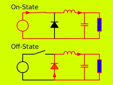
The conceptual model of the buck converter is best understood in terms of the relation between the current and voltage of the inductor. Beginning with the switch open (off-state), the current in the circuit is zero. When the switch is first closed (on-state), the current will begin to increase, and the inductor will produce an opposing voltage across its terminals in response to the changing current. This voltage drop counteracts the voltage of the source and therefore reduces the net voltage across the load. Over time, the rate of change of current decreases, and the voltage across the inductor also then decreases, increasing the voltage at the load. During this time, the inductor stores energy in the form of a magnetic field. If the switch is opened while the current is still changing, then there will always be a voltage drop across the inductor, so the net voltage at the load will always be less than the input voltage source. When the switch is opened again (off-state), the voltage source will be removed from the circuit, and the current will decrease. The decreasing current will produce a voltage drop across the inductor (opposite to the drop at on-state), and now the inductor becomes a Current Source. The stored energy in the inductor’s magnetic field supports the current flow through the load. This current, flowing while the input voltage source is disconnected, when concatenated with the current flowing during on-state, totals to current greater than the average input current (being zero during off-state). The “increase” in average current makes up for the reduction in voltage and ideally preserves the power provided to the load. During the off-state, the inductor is discharging its stored energy into the rest of the circuit. If the switch is closed again before the inductor fully discharges (on-state), the voltage at the load will always be greater than zero.
DC DC Converter Buck Boost:
The buck-boost converter is a type of DC-to-DC converter that has an output voltage magnitude that is either greater than or less than the input voltage magnitude. It is equivalent to a flyback converter using a single inductor instead of a transformer.
Two different topologies are called buck-boost converter. Both of them can produce a range of output voltages, ranging from much larger (in absolute magnitude) than the input voltage, down to almost zero.
The output voltage is of the opposite polarity than the input. This is a switched-mode power supply with a similar circuit topology to the boost converter and the buck converter. The output voltage is adjustable based on the duty cycle of the switching transistor. One possible drawback of this converter is that the switch does not have a terminal at ground; this complicates the driving circuitry. However, this drawback is of no consequence if the power supply is isolated from the load circuit (if, for example, the supply is a battery) because the supply and diode polarity can simply be reversed. When they can be reversed, the switch can be on either the ground side or the supply side.
A buck (step-down) converter combined with a boost (step-up) converter
The output voltage is typically of the same polarity of the input and can be lower or higher than the input. Such a non-inverting buck-boost converter may use a single inductor which is used for both the buck inductor mode and the boost inductor mode, using switches instead of diodes
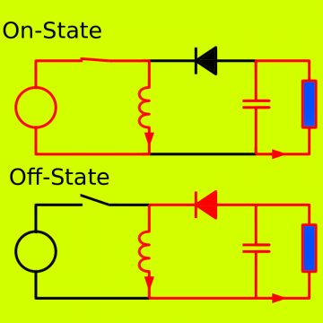
Like the buck and boost converters, the operation of the buck-boost is best understood in terms of the inductor’s “reluctance” to allow a rapid change in current. From the initial state in which nothing is charged and the switch is open, the current through the inductor is zero. When the switch is first closed, the blocking diode prevents current from flowing into the right-hand side of the circuit, so it must all flow through the inductor. However, since the inductor doesn’t allow rapid current change, it will initially keep the current low by dropping most of the voltage provided by the source. Over time, the inductor will allow the current to slowly increase by decreasing its voltage drop. Also during this time, the inductor will store energy in the form of a magnetic field.
DC DC converter Amazon links:
LM2596 DC to DC Converter Adjustable:
20A Power Supply Module DC-DC 6V-40V to 1.2V-35V Step Down Buck Converter Adjustable
Adjustable DC Power Voltage Converter AC 110V-220V to DC 0-48V
*Disclosure: These are affiliate links. As an Amazon Associate I earn from qualifying purchases.
Isolated DC to DC Converter Circuit:
When using a digital measuring instrument with another electronic circuit it is often necessary or desirable to completely separate the supply for the meter from that for the rest of the electronics. The problem can be solved by using two separate supplies, but it can also be done using a single supply and a DC DC converter. The type of converter described here is quite compact and can deliver a current of about 50mA and can boost the voltage from
DC 5V input to DC 7.5V to 12V.
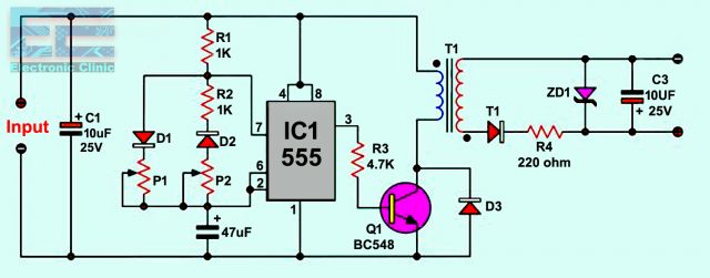
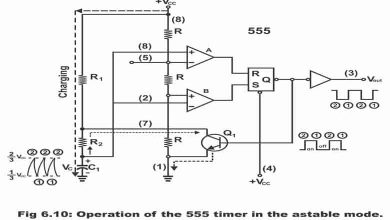
The circuit consists of an astable multivibrator (IC1), which switches the voltage supply for a transformer (Tr1) on and off via a transistor (T1).
The transformer secondary voltage is half-wave rectified and smoothed. The output voltage is then limited by Zener diode D5.
- The transformer used should have a ratio between the windings of 1:1. The firing transformer used for thyristors is ideal for the job, but a small audio transformer (from a pocket radio) is also suitable. The frequency and pulse width of the circuit can be adapted to the type of transformer used by means of P1 and P2. Firing transformers give the best results at frequencies of about 100kHz, while audio transformers usually work best between 0.5 and 40kHz. The transformer must, of course, be connected with the correct polarity.
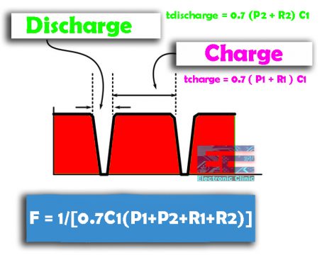
- Charging Time is controlled by P1, R1, and C1.
- Discharged Time is controlled by P2, R2, and C1.
The frequency is found as follows
F = 1/[0.7C1(P1+P2+R1+R2)]
= Hz
Tcharge = 0.7 (P1 + R1) C1
Tdischarge = 0.7 (P2 + R2) C1
Parts you will need:
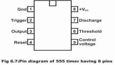
IC1: 555 timer
Q1: BC548, NPN transistor
D1-D4: 1N4148 diodes
C1, C3: 10uF 25V Electrolytic
C2: 0.001uF 50V Ceramic capacitor
0.25W 5% Resistors
R1, R2: 1K
R3: 4.7K
R4: 220 ohms
P1, P2: 100K to 1M potentiometer
DC to DC Converter 12v to 4KV Circuit:
In circuits where two signal paths must be electrically isolated, use is often made of an Optocoupler. Unfortunately, these devices require two power supplies: one for the sender, and the other for the receiver. In industrial and professional undertakings this requirement is met by a proprietary. DC-DC converter. As these are by and large very expensive, they are not of very much interest to the average hobbyist. However, the do-it-yourself converter presented here is
much less expensive and, moreover, easy to build.
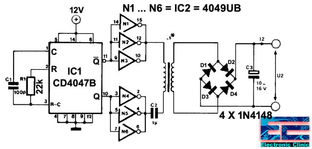
The circuit diagram given above shows that the converter consists of an oscillator, IC, and a Driver, IC2, on the primary side, and of a rectifier, D1… D4, and buffer capacitor, C3, at the secondary.
In our prototype, operating from a 12V battery at the maximum 74 percent Efficiency, we measured a secondary output voltage of 10.64V, and a secondary output current of 9mA (the corresponding primary current amounted to 10.8mA). The secondary current should not exceed 10mA, because the secondary output voltage then drops below 10V and the efficiency deteriorates. That applies also to low-load conditions: when the secondary is open-circuit, the output voltage is 14V, but the efficiency is, of course, 0 percent! In other words: the circuit works optimally at a secondary load current of 9mA.
Oscillator IC1 operates at a frequency of around 100 kHz. Its two output signals are each amplified in three parallel-connected buffers contained in IC2, and then applied to the primary of the isolating transformer. The voltage induced in the secondary winding is rectified and smoothed by C3. The stated value of that capacitor is more than adequate for the relatively high secondary frequency of 200 kHz.
The isolating transformer is a DIY item: it is wound on a pot core of 22mm dia, and 13mm high with 0.35mm dia, enameled copper wire 80 turns for the primary and 80 turns for the secondary. The specific inductance, AL, of the core should be 400nH. The core should not have an air gap. The insulating foil should be placed between the two windings to ensure an isolating voltage of 4KV.
3.3 v DC DC Converter:
The LM3281 is a high-efficiency low-noise miniature DC-DC converter optimized for powering noise-sensitive wireless connectivity chipsets and RF Front End Modules (FEMs) from a single Lithium-Ion cell. The LM3281 is ideal for “always-on” applications with a very low unloaded quiescent current of 16 µA (typ.).
The LM3281 steps down an input supply voltage to a fixed output voltage of 3.3 V with output current up to 1200 mA. Five different modes of operation are used to optimize efficiency and minimize battery drain. In Pulse Width Modulation (PWM) mode, the device operates at a fixed frequency of 6 MHz which minimizes RF interference when driving medium-to-heavy loads. At light load, the device automatically enters into Economy (ECO) mode with the reduced quiescent current. In a low-battery voltage condition, a bypass mode reduces the voltage dropout to 60 mV (typ.) at 600 mA. If a very low output voltage ripple is desired at light loads, the device can also be forced into PWM mode. Shutdown mode turns the device off and reduces battery consumption to 0.1 µA (typ.).
Features
- Operates from a Single Li-Ion Cell (3 V to 5.5 V)
- 6-MHz (typ.) PWM Switching Frequency
- Fixed Output Voltage: 3.3 V
- Up to 1.2-A Maximum Load Capability
- High Efficiency: 94% (typ.) with 3.8-V VINat 300 mA
- Analog Bypass: 60-mV (typ.) Drop-Out at 600 mA
- Low IQ: 16 µA typical, 25 µA maximum
- Automatic ECO/PWM/Bypass Mode Change
- Forced PWM Mode for Low Output-Voltage Ripple
- Soft-Start Limits Input Current on Start-Up
- Current Overload Protection
- Thermal Overload Protection
- Small Total Solution Size: < 7.5 mm2
Check this out: http://www.ti.com/product/LM3281/samplebuy
DC DC Converter 12V to 230V:
So let’s talk about what you want. You want to convert your 12v DC to 230v DC. This means you want to step up magnitude of voltage. Just like the transformer in AC. So we have a circuit which is the dc equivalent of an AC transformer called CHOPPER.
A chopper can convert a fixed DC to a variable DC either in step up or step down form.
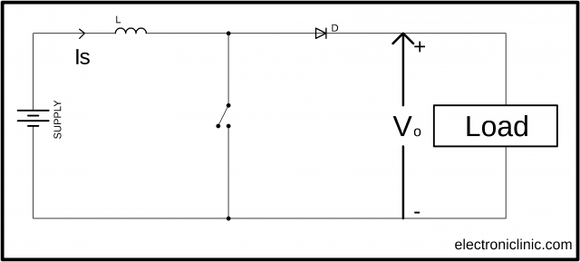
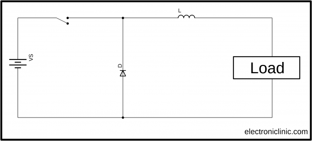
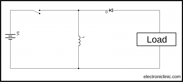
Now we want a step-up chopper (also called boost converter). Here is a chopper circuit of boost convertor.
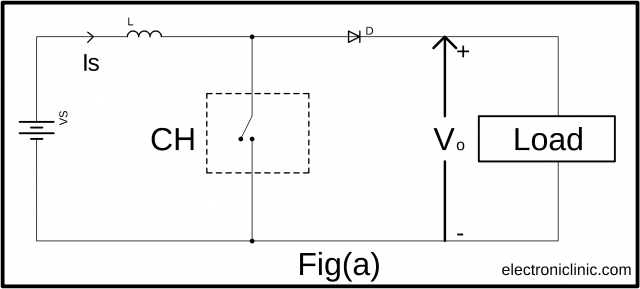
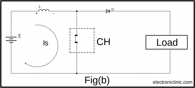
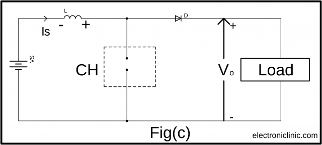
In this chopper, a large inductor L in series with source voltage Vs is essential as shown in figure (a). When the switch CH is on, the closed current path is shown as figure (b) and inductor stores energy during Ton period. When the switch CH is off, as the inductor current cannot die down instantaneously, this current is forced to flow through the diode and load for a time Toff, figure (c).
As the current tends to decrease, the polarity of the EMF induced in L is reversed as shown in figure (c). As a result, voltage across the load, given by
Vo=Vs + L(di/dt)
Exceeds the source voltage Vs. In this manner, the circuit of figure (a) acts as a step-up chopper and the energy stored in L is released to the load.
That is all about the circuit. Assuming linear variation of output current, the energy input to inductor from the source during the period Ton is,
Win= ( voltage across L) ( average current through L)Ton
Win = Vs.Ton( I1+ I2)/2
During the time Toff when the chopper is off the energy released by inductor to load is,
Woff = Toff( voltage across L)( average current through L)
Woff = Toff.(Vo-Vs)( I1+ I2)/2
Considering the system to be lossless these two energies given will be equal.
after equating these two energies we get-
Vs.Ton = Vo.Toff – Vs.Toff
Vo.Toff = Vs( Ton + Toff) = Vs.T
Vo = Vs.T/Toff
Vo = Vs.T/T – Ton
Vo = Vs/ 1 – D ………..(a)
where D is called DUTY CYCLE.
D = Ton/T
It is seen from the equation (a) that average voltage across the load can be stepped up by varying the duty cycle.
Now, you want 230v from the source voltage 12v.
Let’s do some calculation,
you have Vs = 12v
now put different values of D i.e. duty cycle. (Note that the value of duty cycle cannot be greater than 1)
I got the answer when I put D = 0.948.
Vo = 12 / (1-0.948)
after calculating this you will get
Vo = 230.76v
The efficiency of DC-DC converter and calculation:
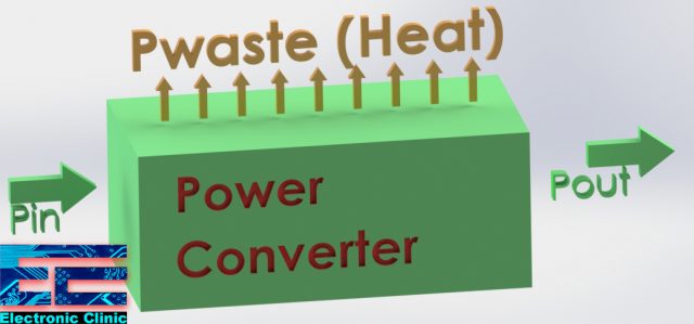
The efficiency of a power converter (DC-DC or AC-DC) is determined by comparing its output power to its input power. More precisely, the efficiency of the converter is calculated by dividing the output power (Pout) by its input power (Pin). The efficiency is usually presented by the Greek symbol Eta “η”. Here is the formula for determining a power converter’s Efficiency (η).
η = Pout / Pin
For example, the efficiency of a converter that provides 500W of output power (Pout) and requires 625W for the input power (Pin), would be 80% (500W/625W=0.80). In this case, the input power exceeds the output power by 125W or 20%, which is lost/wasted power. Therefore, 20% of the input power is converted to heat energy that must be removed from the converter by some means of cooling (conduction, convection, and/or radiation).
Since all power converters have inherent conversion losses, the output power is always less than the input power. Most often, the manufacturer of the power converter specifies its efficiency and maximum output power on the product’s datasheet. When the efficiency (η) and output power (Pout) is known, the end-user can determine how much input power (Pin) will be required and how much power will be wasted (Pwaste) and converted to heat energy under full load conditions.
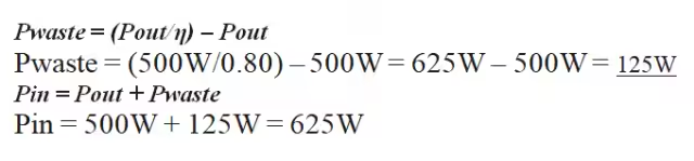
Here are the formulas to determine Pwaste and Pin with sample calculations using the examples listed above.
Obviously, with a higher efficiency converter, Pwaste is reduced. Using the example above, but with improved efficiency of 90% (instead of 80%), here are the revised calculations:
Pwaste = (Pout/η) – Pout
Pwaste = (500W/0.90) – 500W = 555.5W – 500W = 55.5W
Per the examples above, by employing a more efficient power converter it reduces Pwaste from 125W to 55.5W, which provides substantial savings to the user in both electric energy and cooling costs.
Here are alternate formulas for calculating the factors associated with power converter efficiencies:
Pin = Pout/ η
Pwaste = Pin – Pout
Pwaste = Pout (1/ η – 1)
DC DC converter railway:
DC/DC converters are used in railway environments to convert DC battery voltages to a lower voltage for usage in a variety of control and energy circuits. This is because railway rolling stock uses a DC power distribution system so that batteries can be used to maintain electrical power in the event of a generator failure.
These converters need to be constructed according to EN 50155 to ensure harsh environmental conditions do not influence its mode of operation.
Main applications are:
- Railway rolling stock
- On-board and trackside application
- Industrial applications
- High voltage battery-powered applications
- Distributed power supply architectures
What to consider when selecting a DC/DC Converter for Railway?
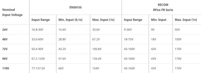
Input Voltage Range
For historical reasons, a large number of different supply voltages are used in railway applications. The most common ratings are 24VDC, 48VDC, 72VDC, 96VDC, and 110VDC.
The latest version of EN50155 defines seven different standardized DC voltages, although 110VDC is the most commonly used on trains. The 24V thru 48V is often used on light railways, trams and trolley buses.
In order to meet these requirements for nominal input voltages, railway application developers opt for 4:1 converters such as the RP20-FR and RP40-FR series from RECOM, as they cover the entire nominal input voltage range with 3 different converter models only.
List of DC DC converter by Recom:
DC DC converter suppliers:
directindustry
cincon
xppower
vicorpower
Mean Well
Mean Well DC/DC converters are used for various purposes, such as transforming socket voltage from 24VDC to 5VDC for microprocessors, stabilizing voltage fluctuations, and simple galvanic isolation. There are countless possible applications and for that reason, the range of DC/DC converters is also very extensive. Dependant on the required design, the technical specifications, and the intended function, Telerex can offer you the right DC/DC converter at an affordable price and supply it quickly.
Mean Well has built up extensive experience and a wide range of designs over the years by supplying DC/DC converters for such varied domains the medical industry, the industrial sector, the railroad industry, the public transportation industry, the military, and the aviation and aerospace sectors.
Overview DC/DC converters
- POL converters and conventional DC/DC converters
- Regulated or unregulated DC/DC converters
- With or without isolation between input and output
- With an input range of 2:1, 4:1, or wider
- Through-hole of SMD-type DC / DC converters
Discover more from Electronic Clinic
Subscribe to get the latest posts sent to your email.
This guide is super informative! I loved the clear explanations and the detailed circuit examples. It’s really helping me understand how to implement DC-DC converters in my projects. Thanks for sharing such valuable insights!
Great post! The detailed explanations of DC DC converters and the circuit examples were really helpful. I especially appreciated the practical tips for selecting the right converter for different applications. Thanks for sharing this valuable information!
This guide on DC DC converters was incredibly helpful! The circuit examples really clarified the concepts for me. I appreciate the detailed explanations and the practical tips. Thank you for sharing this valuable resource!
A DC-DC converter is like a power manager for electronics. It changes one DC voltage to another, making sure devices get the right amount of power. Super useful in everything from phones to solar panels! It’s all about efficiency and flexibility. if anyone wants to know more about Continuous Sandwich Panel!.
nice post