Electrical Wiring, House Wiring or Home Wiring Complete Guide
Table of Contents
Single phase connection in home:
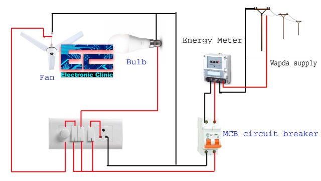
This article is going to be very helpful for you, if you want to learn about how appliances, Motors, Generators, Light bulbs, circuit breakers, float switch, and Contactors are wired up. Single Phase wiring installation is the most common wiring in our homes and residential buildings. The Single Phase supply is 220Vac supply, which consists of 2 wires, one wire is Live and the other one is Neutral. These live and Neutral wires come from the distribution transformer to the energy meter and then directly connected to the main distribution board “MDB” in our homes. Single phase energy meter is connected with pole which receives 220V supply from the step-down distribution transformer. The energy meter is then connected with the distribution box. The distribution box contains different circuit breakers which supplies voltage to different rooms in a house.
In a House we use parallel connections which mean that there will be separate switch for every appliance.
Above is the simplest electrical wiring system for the Fans, Bulbs and outlets. The same wiring system can be used for the Exhaust fans, TV, and other small load electrical household appliances.
Connection of single phase:
- Connect the live and neutral wire from the electrical pole to the energy meter.
- Connect the energy meter with MCB circuit breaker
Finding the proper size for electrical wiring installation:
When we do house wiring we first need to know which size of wire should be used? We know that all conductors and cables have some amount of resistance if we use small gauge wires for high load appliances, the wires will heat up and cause short circuit.
This resistance is directly proportional to the length and inversely proportional to the diameter of conductor i.e.
R ∝ L/A
This equation shows us that when the length of the wire increases its resistance will increase and when the area of the wire increases its resistance will decrease.
A voltage drop occurs in a conductor when current flows through it. Generally, voltage drop may neglect for small length of conductors because small length wire resistance is less but in case of a lower diameter and long length conductors, we know from the equation that resistance is directly proportional to the length when the length of the conductor increases it resistance will increase. We have to take into account the considerable voltage drops for proper wiring installation and future load management.
Wire types:
Aluminium and copper are two commonly used wires. Copper has high in tensile strength, high conductivity, can be easily soldered and is more ductile. Although silver is the best conductor, its use is limited because of its high cost.
Copper is more expensive than aluminum. Aluminum wire has about 60% of the conductivity of copper. It is used in high-voltage transmission lines and sometimes in domestic and industrial wiring. Its use has increased in recent years.
Size of Wires
Wire gauge is used to determine the right size for a specific application because if use wrong size of the wire it can cause damage to the appliance or the wiring system. Sizing of wire is done by the AWG which means American wire gauge system. It tells us the size of the wire and how much current it can safely handle. Common wire sizes are 10, 12 and 14 a higher number corresponds to a smaller wire size, and affects the amount of power it can carry. For example 10AWG wire has 2.588mm diameter, whereas a wire of gauge 20 has a diameter of 0.812 mm. So we can see that as the number increases the diameter decreases so these two are inversely related. A wire of 10 gauge can handle a current of 30 Amperes where wire gauge of 20 can handle 5 Ampere current. So as the gauge number increase the amount of current that the wire can handle decreases. The resistance per length for 10 gauge wire is 1 while the resistance per length for 20 gauge wire is 1 . This shows that when the gauge number is increasing resistance per length is also increasing. For example, a low-voltage lamp will require 18- gauge wire to draw 10 Amperes current, while service panels or subpanels require 2-gauge wire to draw 100 Amperes current.
| AWG | Diameter (mm) | Ampacity | |
| 0 | 0.1 | 8.251 | 125A |
| 4 | 0.25 | 5.189 | 70A |
| 7 | 0.50 | 3.665 | |
| 10 | 1 | 2.588 | 30A |
| 14 | 2.5 | 1.628 | 15A |
| 17 | 5 | 1.150 | |
| 20 | 10 | 0.812 | 5A |
| 24 | 25 | 0.511 | 2.1A |
| 27 | 50 | 0.361 | |
| 30 | 100 | 0.255 | 0.52A |
| 40 | 1000 | 0.080 |
Two way switch connection:
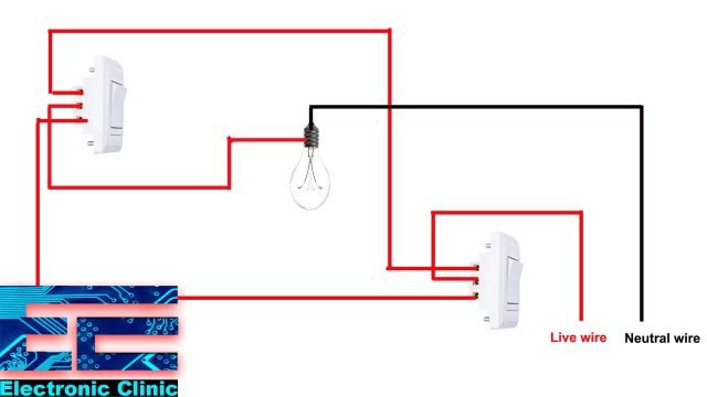
Two way switch connection is usually used in stairs. This type of switch is helpful to use it in top and bottom of stairs or different doors in the room. The switch we generally use in our home has two terminals. While the switch that is used for the two way switch connection has 3 three terminals
- Common
- Line 1
- Line 2
The switch can be flipped in only two ways either up or down.
Components required:
- 2 two way switches
- Bulb
- wires
Working of two way switches
Let suppose that we are controlling a light through 2 switches. Connect the live wire with the common of switch 1. Connect the bulb one terminal with common of the second switch and other terminal of the bulb with the neutral wire. Now connect the L1 of switch one to the L2 of the switch 2. Connect the L2 of switch 1 with L1 of switch 2.
This work like exclusive OR gate.
- When the common of Switch one is connected with L1 and common of switch 2 is connected with L2 then the circuit will be completer and bulb will be turn on.
- When the common of switch one is connected with L1 and common of switch 2 is connected with L1 the circuit will be broken and bulb will be turn off.
- When the common of switch one is connected with L2 and common of switch 2 is connected with L2 the circuit will be broken and bulb will be turn off.
- When the common of switch one is connected with L2 and common of switch 2 is connected with L1 the circuit will be complete and bulb will be turn on.
| Switch 1 common | Switch 2 Common | Light |
| L1 | L2 | ON |
| L1 | L1 | OFF |
| L2 | L2 | OFF |
| L2 | L1 | ON |
Single phase motor two way switch wiring:
There are situations when you need to control a single phase motor “Water Pump” from two different locations “two houses, two floors, etc”. In a situation like this the single phase motor wiring is done in such a way that if the motor is turned on from one location it cannot be turned off from the other location. In this system we have created interlock system such that if the motor is on from one home it cannot be turned ON from the other home until it is turned OFF from the first home. The great advantage of this interlock system is that if there is change in line and neutral no short circuit will occur.
Working of single phase motor two way switch:
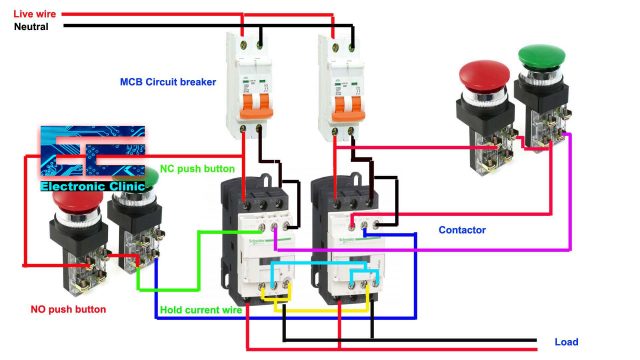
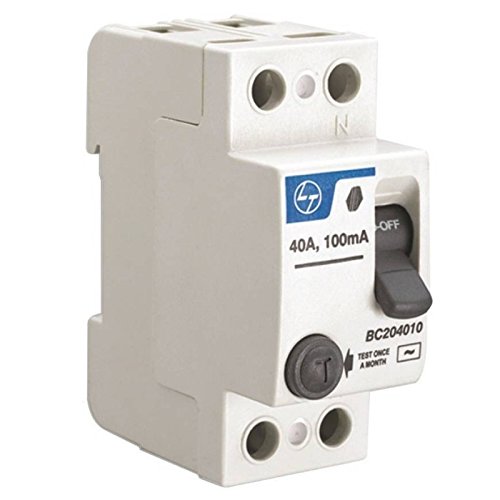
The neutral and live wires that come from the main energy meter are connected to the double pole MCB circuit breakers. The purpose of using double pole MCB circuit breaker is that if we want to change any appliance, machine or load, or we need to repair something in the circuit, we can easily turn off the supply through the MCB. Contactor will be used to turn ON and turn OFF the motor, it is used for the interlock system which is not possible if we use a relay or a starter. This contactor has 3 poles. The neutral and phase wires at the output, from both the contactors are common.
Contactor coils are labelled as A1 and A2. We will take a wire from the neutral of contactor and give it to the A1. We will use contactor to our requirement for example as our supply is 220V we will use such contactor which make coil magnet from 220V. We will use two buttons for ON and OFF. Red button for OFF and green button for ON. The Red buttons used are of the type normally closed and the green button used are of the type normally open. In these buttons we have both open and close contacts. For red button we will use close contacts and for green button we will use open contacts.
Connect the phase supply to the close contact of the red button. Connect the other terminal of red button to the open contact of green button through a wire. Now we will make hold current wire by connecting the green button with the normally open contact of the contactor. Now we will create interlock system such that when first contact will be energized the other contact will not be energized. We will connect the green button terminal with the normally closed of the second contactor. Connect the bottom normally closed of the second contactor with the bottom of first contactor normally closed terminal and also to the A2 contactor on the first contactor. Now connect the bottom normally closed of the first contactor with the A1 and A2 of the second contactor.
When we will give supply through green button it will come to the second contactor normally closed contact, if this contactor is de-energized then it will came to the bottom of normally closed contact which is further connected with the A1 and A2 coil of the first contactor which will make first contactor coil energized. Then in normally open contact we have hold wire now internally normally open contact will become closed. This contactor will be remaining energized until we turn off the push button. By using this system short circuit problem will be finished. The same procedure will be used for the second contactor.
Wire calculation for motor:
Wire Size calculating:
To calculate the wire size for motor we must know the following values:
Load
Voltage
% Efficiency
Motor efficiency is usually mentioned on name plate of the motor.
Cable size calculation for single phase motor:
Let suppose that:
Load = 1KW
Voltage = 230V
% Efficiency = 80%
We know that
cosΦ is the power factor which is equal to 0.8
P=VI cosΦ×efficiency
Now we will calculate the current
I=P/(V×cosΦ×efficiency )
I=1000/(230×0.8×0.8)
I=6.79A
Every single phase motor has 2% current drop.
Current drop = 6.79×0.02
Current drop = 0.1358A
Total current=6.79+0.1358=7 A
To calculate wire size we normally used two types of conductors copper and aluminium wire.
For Aluminium wire:
1 sqmm=1.5A
So for 7A the wire size will be 7/1.5=4.66 sqmm
For copper wire:
1 sqmm=2.5A
So for 7A the wire size will be 7/2.5=2.8 sqmm
Cable size calculation for three phase motor:
Let suppose that:
Load = 10KW
Voltage = 440V
% Efficiency = 80%
We know that
cosΦ is the power factor which is equal to 0.8
P=√3× VI cosΦ×efficiencyNow we will calculate the current
I=P/(√3×V×cosΦ×efficiency )
I=10000/(√3×440×0.8×0.8)
I=20.5 A
Every three phase motor has 5% current drop
Current drop = 20.5×0.05
Current drop = 1.025A
Total current=20.5+1.025=21.52 A
To calculate wire size we normally used two types of conductors copper and aluminium wire.
For Aluminium wire:
1 sqmm=1.5A
So for 21.52A the wire size will be 21.52/1.5=14.34 sqmm
For copper wire:
1 sqmm=2.5A
So for 21.52 A the wire size will be 21.52/2.5=8.608 sqmm
Single Phase Submersible Pump Starter
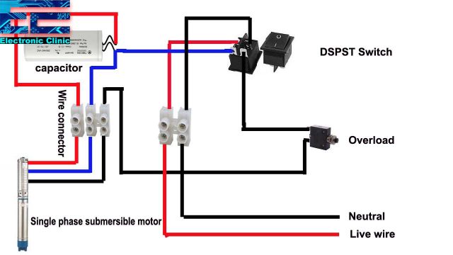
The submersible motor are one of the most commonly used motors. For the Single phase Submersible Water Pump we will need the following components in the Distribution box.
Overload protector:
This thermal over load protector work when over current flow through it. It consist of bimetallic strip when over current flow through it break the circuit.
DPST switch:
DPST is double pole single throw switch. This switch work like double pole circuit breaker we can also use double pole circuit breaker in place of it.
Capacitor:
Capacitor is connected with the motor as it is single phase induction motor so it require capacitor ,at start up it provide leading power factor to the motor.
Connection of Submersible motor:
The neutral will be connected with the switch top terminal from the bottom terminal of the switch we will connect capacitor and the other terminal of capacitor will be connected with the motor. The line wire will be connected with the switch other terminal at the top. From the bottom terminal of switch we will connect overload protector the other terminal of overload protector will be connected with the motor. The other terminal of capacitor will be also connected with the motor.
Float switch automatic water level:
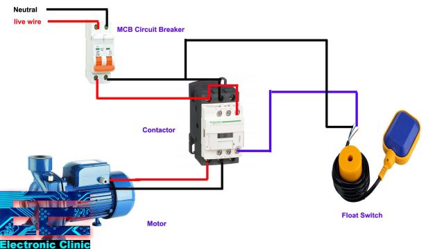
Float switch is connected with motor so that it can automatic turn on and off according to the level of water tank. The float switch is installed in water tank, when the level of water is decreased in the water tank, float switch give signal to the motor to turn on and when the water tank is full the float switch give signal to the motor to turn off.
Components required:
- Float switch
- Magnet contactor
- Overload relay
- Double pole MCB
- Single pole MCB
Float switch connection
The float switch consists of three wires. To check the float switch we will set the Multimeter on continuity it contains red, blue and black wires in which black is neutral wire. We will connect the multimeter one probe with the black wire and the other with the blue wire when the float switch will be at bottom it will act as closed circuit and give signal to the motor to turn on. It give beep on multimeter which show that it act as closed circuit. Now connect the one probe of the multimeter with the black and other with the red wire when the float switch will move upward it act like a closed circuit.
Float Switch Working :
We will connect miniature circuit breaker (mcb) which automatically switches off electrical circuit during an abnormal condition of the network means in overload condition as well as a faulty condition with live and neutral wire at input. Connect the output of the mcb with the contactor input. Magnetic Contactor is for lossy magnetic flow generated with current in winding of such devices as transformer, throttles, magnetic cartridges filters and circuit. Output of contactor is connected with the motor. Connect the wire of the float switch with the neutral wire. Connect the L1 of the contactor with the A1. Connect the blue wire of the float switch with the A2 of the contactor.
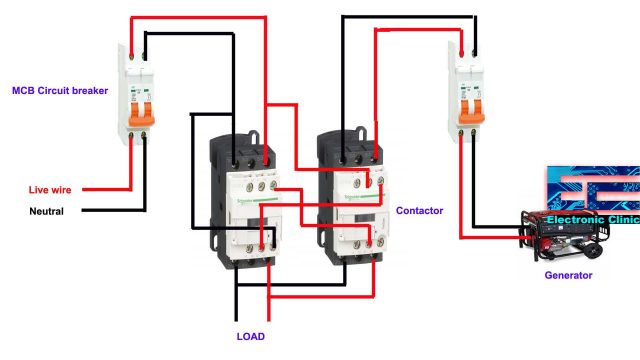
Automatic changeover switch for generator:
A smart way to build an automatic transfer switch is by using two contactors together. It is about two, electrically controlled, circuit breakers. The contactors are not allowed to close simultaneously, but only one at a time. The two contactors are joined together with a ‘mechanical interlock’ mechanism. It will not allow to both relays of the contactors to be in a ‘closed position’. Connect the main supply of the meter with circuit breaker input. Connect the mcb circuit breaker output with the contactor L1 and L3 terminals. Connect A2 of the contactor with neutral. Now connect the phase and neutral from the generator at circuit breaker input. Connect the circuit breaker output with the second contactor at L1 and L3. Connect the bottom normally closed NC of the bottom with the A1 of the second contactor. Connect the NC of the first contactor with the generator phase line. Connect A1 of the first contactor with bottom NC of the second contactor. This system will form a magnetic interlock. Now connect the bottom of both contactors from where we can connect our load.
