Ladder Logic Programming Software free download & how to use “WinProLadder”
Ladder Logic Programming Software Description:
Ladder Logic Programming Software– I have worked on so many PLC and SCADA based projects which I want to share with you guys. But before I share any basic or complex level PLC based project, first, I want to explain the extreme basics. This is my first tutorial on the PLC ladder logic programming and I am supposed to start with the very basic things that I believe every beginner should know about. In this tutorial, I will cover
- Why I prefer FATEK PLC for beginners?
- What is the best Ladder Logic Programming software for beginners?
- Ladder Logic Programming Software free download “WinProLadder”
- How to use the WinProLadder software?
- How to write your first Ladder Logic Program using WinProLadder?
- How to use comments in ladder logic programming?
- How to run a simulation in WinProLadder?
- How to upload a program in Fatek PLC.
Without any further delay let’s get started!!!
Amazon links:
Fatek PLC, FBs-14MAR2-AC (FBs-14MA):
IR adjustable infrared Proximity Sensor 2v to 24V:
Other Tools and Components:
Super Starter kit for Beginners
PCB small portable drill machines
DISCLAIMER:
Please Note: these are affiliate links. I may make a commission if you buy the components through these links. I would appreciate your support in this way!
Best PLC for beginners?
When it comes to the PLC training/learning, the very first question that pops up in our mind is, which PLC should I start with? I myself have been through this stage. In the beginning, I was really confused which PLC to start with as there were so many PLCs available in the Market like
Siemens PLC, Omron PLC, Keyence PLC, and Fatek PLC, etc. After doing some research work I find out that Fatek PLC is best in terms of price and use. There is no doubt that today Siemens and Omron are at top of the list, but over here the question is which PLC is best for the beginners? The ladder logic programming of all the PLCs is exactly the same, only the addresses can be changed, and the names of the inputs and outputs, while the logic remains the same.
If you start with the FATEK PLC it really doesn’t mean that in the future you won’t be able to write programs for the Siemens, Omron, and Keyence PLC. The ladder logic programming is exactly the same the difference can be in prices, memory, the number of timers and counters, the names/addresses of the inputs and outputs. At this point, you really don’t need to pay any attention to all these things. Your only focus should be how to easily learn the ladder logic programming.
I started with the Fatek PLC and I have no problem in writing programs for the other PLCs, I just read the manuals, check the inputs and outputs and some technical specifications and that’s it.
Let me give you an example of the Keyence PLC and Fatek PLC ladder logic program,
This is the ladder logic program of the Keyence PLC. The inputs are 1010 and 1011 while the outputs are 0500 and 0501. The same program in the Fatek PLC will be like
As you can see the ladder logic programming is 100% same, only the names of the inputs and outputs are different. In Keyence PLC 1010, 1011, etc are used to represent the inputs while in Fatek PLC X0, X1, ….Xn are used to represent the inputs and similarly y0, y1….yn for the outputs. The only thing that I want to explain is, the ladder logic programming is the same for all the PLCs, so it really doesn’t matter which PLC is in front of you. Once you learn the ladder logic programming for the FATEK PLC then you can download the simulation software’s of other PLCs and test your programming skills.
For the beginners, I always suggest Fatek PLC as its cheap and very user-friendly. In all of my upcoming PLC-based tutorials, I will use Fatek PLC, FBs-14MAR. I will write a complete article on the Fatek PLC.
WinProLadder PLC Software:
WinProLadder software is one of the best PLC programming software throughout the world. I always use WinProLadder Software for the Fatek PLC ladder logic programming. WinProLadder is an ideal PLC programming Software for beginners. If you don’t have a PLC it really doesn’t matter because in WinProLadder we have the simulation option. So you can write a ladder logic program and run the simulation to check your programming.
In this tutorial, I will explain all the basic things that you will always need. Before I start with the WinProLadder software, I recommend you should first download the WinProLadder software given below.
Download WinProLadder Software:
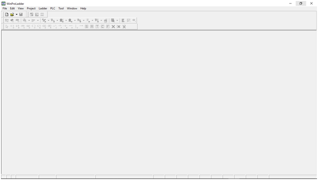
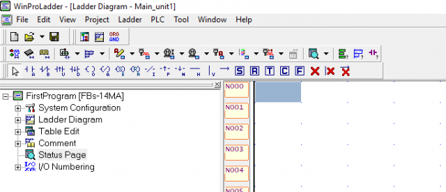
After you are done with the installation, open the WinProLadder software and this is how it looks like.
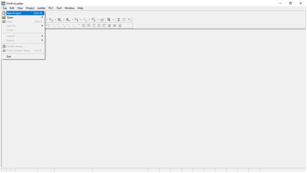
To start a new project simply click on the File Menu and then click on the New Project or you can press Ctrl+N on the keyboard.
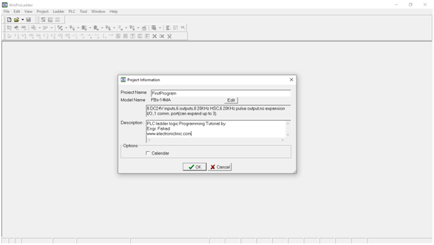
This will open the Project Information form
Enter the Project Name, select the PLC Model by clicking on the edit button. I select FBs-14MA as I will be using this PLC. 14 means that this PLC has a total of 14 input and output ports. Out of 14, 8 are the inputs and 6 are the Outputs. I will talk about this in detail in my next tutorial. After writing the description then you can click on the Ok button.
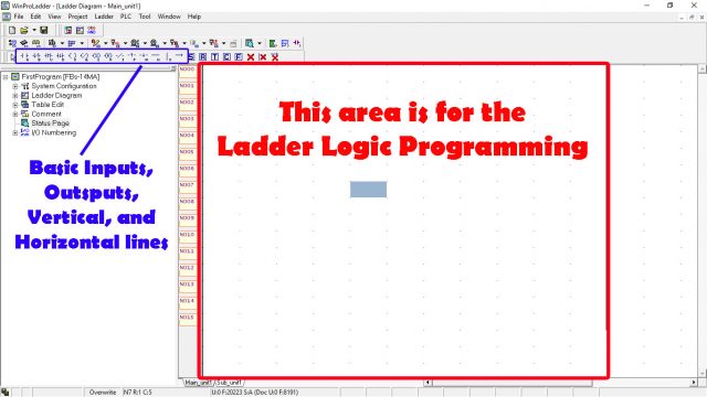
The contacts A, B, U, and D are used for the inputs. While the contacts O, Q, E, and R are used for the outputs.
For now, let’s concentrate on how to write a very basic Ladder Logic program. Lets, for example, we have an Infrared Sensor which is connected with X0 of the Fatek PLC and a 220Vac Bulb which is connected with the Y0 Output Port of the Fatek PLC.
Now the task is we have to turn ON this Bulb for at least 5 seconds each time the infrared sensor is activated. This project can be used in a staircase when someone crosses the infrared sensor the light will turn ON for 5 seconds. For this we don’t need any hardware we will check this using a simulation.
while the network N000 is selected, now to select the input contact “A” simply use your mouse, click on the contact “A” and then click on the Blue area next to the N000. Or you can use a short cut by simply pressing “a” on the keyboard.
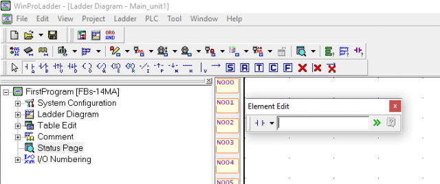
You will see the element edit, click on the arrow to expand it.
Enter X0, you can see the X0 color is green which means it’s a valid input. Enter the comment and description and click on the ok button.
As you can see the input X0 is added.
Now to add the output select the area next to the input X0 and click “o” on the keyboard or you can click on the contact “O” using your mouse left button and then click on the blue area.
After you click on the blue area the Element Edit form is opened.
Enter the output Contact which is Y0, write a comment and also write some description. Always write comments and descriptions because it will really help you and others when they read your program. Finally, click on the Ok button.
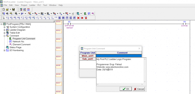
This is how it will look like. There are no input and output comments, we need to enable them. For this go to the View menu and click on the Element comment. As you can see in the picture below, now the comments are visible.
As you know comments are optional but it’s a good programming practice to use comments. Now anyone can clearly understand that with X0 input the infrared sensor is connected and with the output, Y0 220Vac bulb is connected.
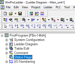
You can also add Program Unit Comment and Network Comment. To add these comments on the left side you can see comment above the Status Page.
Click on the Plus sign next to the Comment to expand it.
Click on the Program Unit Comment and then click on the Blue area next to the Main_unit1 to add a comment. Write anything you want to display and then click on the Ok button.
Now to add the network No comment, simply click on the Network No and write anything you want, but remember it should be meaningful.
So now that you know how comments are used in the WinProLadder Software. Now let’s check this program. To run the simulation click on the PLC menu and then click on the Simulation, again click on the PLC menu and then click on the Run.
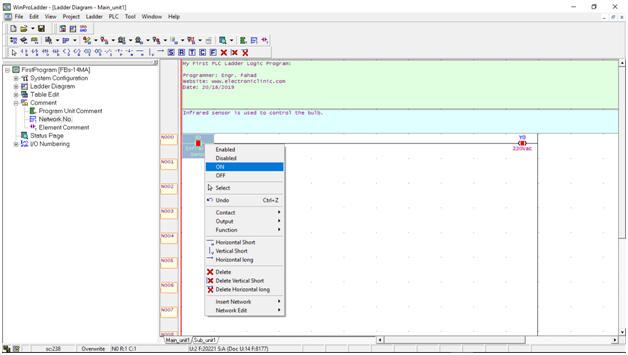
Now to turn ON and Turn OFF the input simply select the input first, and then click the mouse right button and then click on the ON or OFF. As you can see in the picture below when the input is ON the OUT is also ON.
But our task is to turn ON the bulb only for 5 seconds and then turn it OFF. For this, we can use a timer. Now to stop the simulation go to the PLC menu and click on the Stop. Now to add a timer we will need to make a branch. For this select the line and click on the “v” key on the keyboard which is used for the vertical line. This will make a branch.
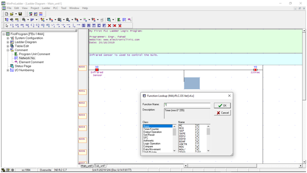
Then select the bottom side of the vertical line and press “f” on the keyboard this will open the function lookup. In the function name type T as you can see in the description there is a total of 0 to 255 timers, click Ok.
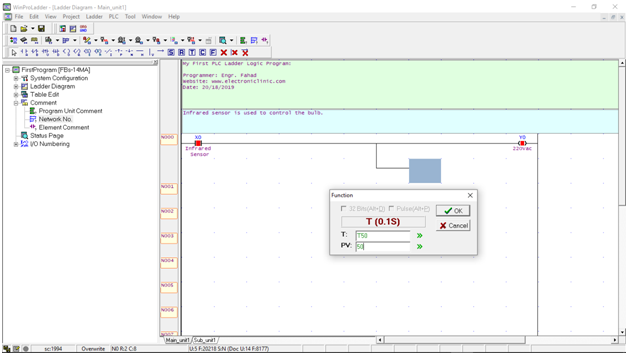
This will open another dialog box, enter the time number, I will be using T50 and the pre-set value of 50 which is equal to 5 seconds as 50 x .1 = 5 and then click on the ok button.
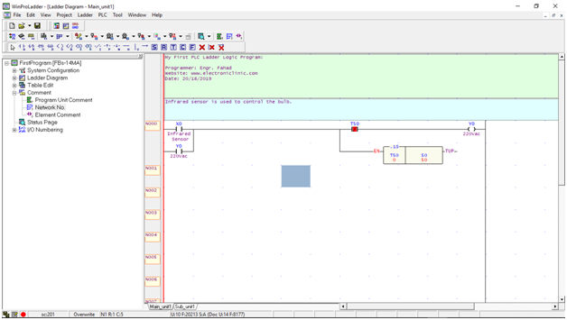
Add another input and enter y0 as the feedback. And another input as T50 as you can see it has a line. To add such type of the input you will need to enter “b” on the keyboard and then type t50.
How to Upload the Program in Fatek PLC:
Before you upload the program, first of all, make sure that your PLC is connected with the computer / Laptop, then go to the PLC menu and click on the online button. For this, you can watch the following video available on my YouTube channel.
The purpose of this tutorial was to explain the most basic things like how to start a new project, how to select a PLC model, how to write comments, how to run the WinProLadder simulation and how to upload the program. This is not possible for me to explain everything in a single Tutorial. I will make a complete series of tutorials. I will also make some complex level projects.
Download the PLC Ladder Logic Program file: plc program file
Video Demonstration:









Thanks!! It was really helpful. Now I get the basics of PLC
Very Good , Fahad Bhai , Nicely explained. Many Thanks, Sharad (India)
I really enjoyed the simplicity of your explanation. Am completely to this and I wish to learn from you and want you to be my mentor.
Hi Fahad, thank you for the clear walkthrough.
Quick question though. In your video it shows the timer counting up in red in the timer block and I like that visual feedback while running the program. Was there something that you did to make that show? On mine everything works perfectly, but there is no visual timer that counts up. Also, on mine there is an automatic Program Unit Comment that was added under the “EN” on the timer and the “T50” b input that just says “timer”. Is this a matter of the program version? I downloaded the V3.31 version updated 9/20/2023 from the Fatek website.
Thanks again,
Kent