Surface mount technology SMT Explained
Table of Contents
Surface mount technology (SMT):
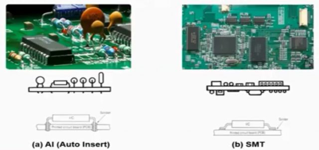
Surface mount technology SMT means the technique of directly mounting the electronic components to the surface of printed circuit board. In the through-hole technique, the leads are inserted in PCB and hence the problem were automatically encountered if the leads are not fitted properly which slow down the production rate. All electronics products demand more function with small size. So circuit PCB became more compact. The leads that have been used for connections were removed and the components are directly soldered on the paths of the PCB which saved the cost of making holes in PCB. This article is based on the video from SMT Know-How YouTube channel.
Surface mount technology SMT Process Flow:
Surface mount technology is a totally automated process that starts from the loading of bare PCB and ends with mounted product. The machine used in the SMT process are:
PCB loader:
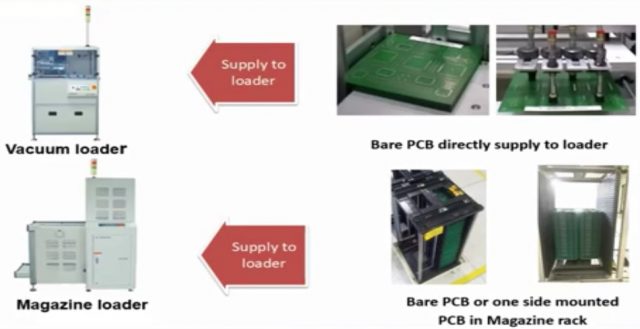
The first machine of Surface mount technology SMT line is the PCB loader. Here the bare recipes are loaded in the magazine rack and supply to load the machine. The machine then automatically supplies the bare board one by one to the next process. In Surface mount technology SMT maximum scrap is produced by the loader and un-loader due to its wrong setting. There are two types of loader:
- Vacuum loader:
It is used only to load bare PCBs means a PCB without any assembly.
- Magazine Loader:
It is used to supply bare PCB here we will put manually PCB in the rack.
The maximum company used magazine loader only because if we add vacuum loader together the line length gets increase but we suggest to use vacuum loader so the time rate is decreased.
PCB cleaner:
As you know the dust can create defects during the SMT process hence removing the foreign particles from the PCB. A PCB cleaner machine is added after the loader and before the printing process.
at SMT line
Gate Conveyor:
The gate conveyor is used when the line is too long and the operator needs to move the front of the line it will reduce the transfer time.
Turn Conveyor:
The PCB flipper is also called a turn conveyor as per the production requirement. The turn conveyor machine is used to automatically turn the PCB for the next process basically it is attached between the two lines connected in series after the completion of one side product the PCB is flipped upside down and the second side production is done.
Inspection conveyor:
An inspection conveyor is used to check the overflow of the PCB.
Link conveyor:
It is used to link one machine with another machine.
Solder printer:
The next machine is a solder paste printer the same machine can be used for blueprints. Here the solder pastes the base form of soldering wire is printed on the bare PCB through a stencil mask. So that the solder paste is printed on the PCB. The manual, semi-automatic and fully automatic printers are available in the market. The manual and semi-automatic printer is an offline machine and commonly used in Surface mount technology SMT production because PCB loading and unloading is done manually. The automatic printer has functions like automatic PCB loading.
In SMT 80% of defects are related to the solder paste printer.
Inspection machine:
The next machine is an inspection machine which is used for quality filtration. Here the printing condition is inspected by a solder pest inspection machine which is also called SPI.
Pick and place machine:
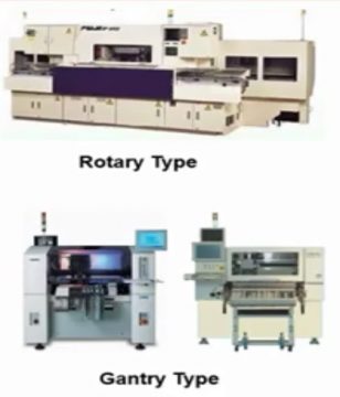
Next is the pick and place machine also known as mounter is used for mounting the various component the surface mount devices like resistor capacitors diode transistors ICs are placed on the PCB where the solder paste is already printed. There are three types of pick and place machines:
Rotary type machine:
In this type of machine, the table moves in the XY direction and the head moves in the Z direction. Here head picks the component and place it on the PCB. Today the production of the rotary machine is stopped due to the limitation of the cycle time because It has a huge size and weight.
Gantry machine:
It is gradually used as multi-mounters for small quantity production. Multi mounter is the machine that is used for mounting chips and class components.
Module type:
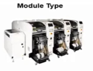
As the rotary type has a cycle limitation module type can increase the capacity of the production. It has the advantage that it requires a smaller area. The number of modules are attached to increase the capacity.
Reflow oven:
After component placement, the PCB is passed through the reflow open here the solder paste gets melted and forms the joint between the PCB pad and components. This machine is used for soldering the surface mount to the print circuit board. There are different types of reflow ovens available in the market.
Automated inspection machine:
Next, the automated inspection machine which is also known as AIO the inspection is done to verify the soldering and placement condition of the product.
X-ray machine:
X-ray inspection machine is the equipment that is used to check the soldering condition and path which is impossible with a visual inspection.
PCB unloader:
The last machine is the PCB unloader this is the last process of SMD where the soldering is done PCBs are stored in magazine racks. The PCB unloader is used to unload the semi-furnished or furnished PCB. It is available in magazine type only. This machine is placed at the end of the assembly line.
Why SMT is required?
SMT is a very important process because all electronic products start from SMT the products like television, laptop, refrigerator, washing machine, mobile phones, and automobile products which works on electronic circuits are produced by Surface mount technology SMT process as electronic products are becoming more and more compact the SMT process became more critical.
Growth history of the Surface mount technology SMT:
The history of electronic circuits with respect to the component size. In 1950 the first generation components were tube-type large high voltage devices. In 1960 the second generation axial type lead components were introduced. In 1970 radial type components and integrated components were developed which are used in mobile devices. By the fourth generation, compact high-density devices were introduced which are called surface mount parts. In 1990 the fifth generation ultra-compact high-density devices came into the market with complex surface mount components. In the 2000 century, more high-density and compact devices thinned multiplexed high-speed mounting components are introduced.
Surface mount technology SMT started in the 1980s and from that time continuously made further progress in the technology with the demand of the compact product. The size of the component got reduced from
Also the class components from:
From 2018 global OEMs kept from china and spread to Vietnam, Indonesia, and India where manufacturing cost is less with that Surface mount technology SMT factories are also getting transferred but the main hurdle is that these countries are not yet ready with the skilled manpower worldwide SMT process training is not yet available hence they learn individually but developing countries not have experience from where to get the correct training by which they can upgrade their manpower skill.
SMDs components:
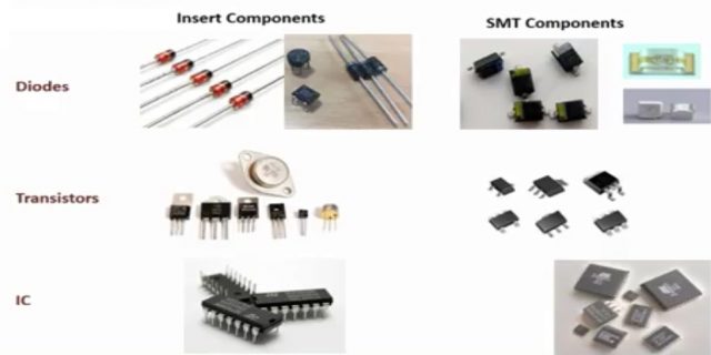
SMD components are usually smaller than its through-hole counterpart because it has either smaller leads or no leads at all. Let’s compare the through-hole components with SMD. Through-hole resistors have two leads visible at both ends of the component body while the SMD resistors have pads on their body itself. Similarly, the SMD ceramic capacitors have leads on their body few capacitors like electrolytic capacitors have flat leads. The SMT inductors are looked the same as that of capacitors. It is difficult to distinguish the inductors and capacitors visually the leaded SMT components have flat leads which are mounted on the surface of PCB.
These are the different types of transistors with two three four or five leads. The SMD devices may have short pins or leads of various styles flat contacts and a matrix of solder balls or terminals on the body of the components.
Size classification:
As explained SMT components are usually smaller than through-hole components and are designed to be handled by machines rather than by humans. The electronic industry has standardized the package shapes and sizes here the sizes of components is explained as per its packages.
| Package (mm) | Length (mm) | Width (mm) | Package (inch) |
| 1005 | 1.0 | 0.5 | 0402 |
| 1608 | 1.6 | 0.8 | 0603 |
| 2012 | 2.0 | 1.2 | 0805 |
| 3216 | 3.2 | 1.6 | 1206 |
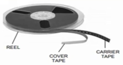
The 1005 size is in mm and 0402 is in inches we suggest using mm because the machine uses an mm unit. So do not get confused you need to use the common unit only. In smartphones, 0603 sizes are also used from packet size. You can recognize the component size for example in the case of the 1005 size package component it has 1.0 mm length and 0.5 mm width. Similarly, in the case of 1608, the length is 1.6 mm and the width is 0.8 mm. In the case of 3216 the length is 3.2 mm and the width is 1.6. Here thickness is not included exact size need to be used while making the part data in machine automation of surface mount assembly by the use of a pick-in-place machine to handle tiny components has been enhanced by evolutionary improvement in tape and reel systems which can accommodate as many as 4000 parts on a 13-inch reel. This results in less frequent component reloading and less downtime of the assembly equipment. Other advantages of tea feeders include versatility or the ability to handle a variety of parts.
The SMT components are packed in a reel or a spool form the different types of spools available are the paper types used for standard package components only. The Emboss type for other and semiconductor materials depending upon customer requirement the ICs are packed in a stick form tray form or a spool form.
