Types of Logic Gate and its Applications
Last Updated on October 10, 2023 by Engr. Shahzada Fahad
Table of Contents
Types of Logic Gates
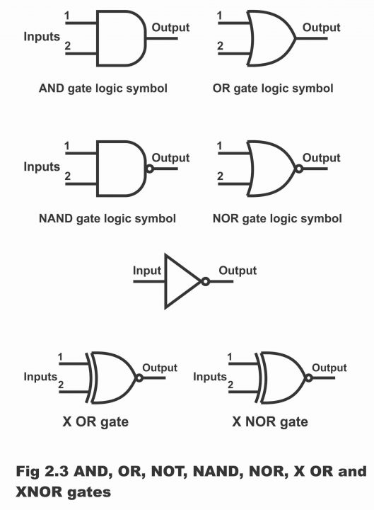
Types of Logic Gate and its Applications- The logic gates have the following types according to their function or working
Figure 2.3 – AND, OR, NOT, NAND, NOR, X OR and X NOR
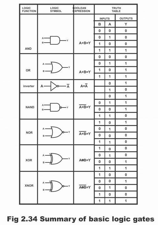
Different Types of Logic Gates
In figure 2.34, a summary of different types of logic gates has been presented.
Applications of logic Gates
The range of usage of logic gates is quite extensive, however some of its distinct applications are as follows:
- In manufacturing more complex devices e.g. binary counters etc.
- In decision–making regarding automatic control of machines and different industrial processes
- In calculators and computers
- In digital measuring techniques
- In digital processing of communications
- In musical instruments, games and different domestic appliances
Logic Gate Families
A large number of digital systems are designed by mixing a number of different logic functions (e.g. OR, AND, Inverter, NAND, NOR, XOR and XNOR). All such logic circuits are available in IC modules and these modules have been distributed into different families. Every family is denoted by a few short words or abbreviations, which indicate the type of logic circuit being used in this family. For example, RTL means resistor, transistor logic. These days, the following seven transistor logic families are more famous, though the usage of the first two of these seven families has become confined or almost finished these days. However, here these are narrated just from the point of view of a historical perspective.
- Resistor Transistor Logic (RTL)- This was the first family group of logic circuits, which was developed and packed in the shape of IC in 1960 (that’s it was manufactured in the shape of an IC and was closed in an IC packing)
- Diode Transistor Logic (DTL) – it was manufactured after RTL in the end of 1960.
- Transistor- Transistor logic (TTL or TL)- It was introduced in the beginning of 1970
- Shot Key TTL- It was manufactured in order to enhance the speed of TTL
- Emitter Coupled Logic (ECL) – This is the fastest logic line amongst all the logic lines available these days.
- Integrated Injection Logic (IIL) or (IL) – This is the latest form of bipolar types of logic
- Complementary Metal Oxide Conductor (CMOS) – This logic circuit is very famous and popular due to its least power consumption feature as compared to all other available logic circuits. Moreover, these are also less costly and quite speedy.
Prior to knowing the details (which is coming ahead) of different logic families, it is essential to understand its various characteristics, because all families have different characteristics.
Saturated and Non-saturated logic
Logic circuits, in which transistor function or drive in a state of saturation, are known as saturated logic circuits or simply saturated logic. One of the disadvantages of this circuit is that when transistor is brought out from its saturation state, they take some time in coming out from that state. (i.e. when a saturated circuit is turned off, it does not turn of instantly, rather it tends to turn off after some delay, which is its greatest demerit). It is because when a transistor saturates, in such a situation its base is flooded with majority carriers (by means of which an extensive current continues passing through it), until even if the base voltages are turned off, as has been revealed in the figure 2.35, even then the flow of carriers from its base tends to continue for some time. That’s if its base voltages are turned off for turning the transistor off, even then its base remains flooded with carriers as the base requires some time for these carriers to flush out completely (i.e. even after transistor turns off, carriers keep transmitting through the base for quite some time, until all carriers have been depleted). In case of saturation, the time required for the current carriers existing on any transistors’ base, pushing out from the transistor’s base, after it has been turned off, is known as saturation delay time (Ts). (In simple words, the time required for ejecting out carriers present on the base of a transistor, is called saturation delay time). Therefore, due to this very reason, the switching speed of a saturated logic circuit is low. Transistor transistor logic circuit (TTL) is an example of saturated logic circuits.
Figure 2.35 – switching action of transistor
![]()
The logic circuits, in which transistors function in a state of non – saturation (or the logic circuits, in which transistors are protected from its saturation), are called non–saturated logic circuits. The switching speed of such circuits is very fast (that’s in situations of non – saturation, a transistor turns off abruptly, therefore, this circuit is enormously speedy because of its very low delay time). Remember that ECL (emitter coupled logic) is an example of non – saturated logic circuit.
Previous Topic: Exclusive NOR Gate or XNOR Working Principle & Circuit Diagram
Next Topic: Selection of Logic Gates or Digital Integrated Circuits
For electronics and programming-related projects visit my YouTube channel.
Discover more from Electronic Clinic
Subscribe to get the latest posts sent to your email.


i like the knowledge gained
same ;3
Great post! I found the explanations of the different types of logic gates really helpful, especially the examples of their applications in real-world scenarios. It’s fascinating how these fundamental components play such crucial roles in modern electronics. Looking forward to more insights on this topic!