0-25V Voltage Sensor with Arduino, Battery Voltage monitoring
Last Updated on September 21, 2024 by Engr. Shahzada Fahad
Table of Contents
Voltage Sensor with Arduino:
0-25V Voltage Sensor with Arduino, Voltage monitoring- In this article, you will learn how to use a 0-25V voltage sensor with Arduino to display the measured voltage on an SSD1306 OLED display module. I am also going to explain how to turn ON a buzzer when the voltage level increases or decreases below a predefined value.
Voltage sensors are used to measure the voltage level of a power supply or battery. They are commonly used in electronic circuits to monitor voltage levels and trigger alarms or control circuits when voltage levels reach critical levels.
Let’s say if you are charging a battery and there is no automatic disconnection system then using this 0-25V voltage sensor you can build yourself an automatic voltage disconnection system or you can turn on a buzzer or send yourself an SMS using a GSM module, or Blah Blah Blah just tell the Arduino to inform you.
Using a 0-25V voltage sensor with Arduino and an OLED display module can help you easily monitor and display voltage levels in real-time.
This voltage sensor is capable of measuring voltages ranging from 0.02445v to 25V DC. Later in this video, I will also explain how to modify this Voltage Sensor for measuring high voltages. Anyway for now, let’s stick to the voltages ranging from 0.02445V to 25V volts DC. So, without any further delay let’s get started!!!
Amazon Links:
Arduino Nano USB-C Type (Recommended)
*Disclosure: These are affiliate links. As an Amazon Associate I earn from qualifying purchases.
About 0-25V Voltage Sensor
A 0-25V voltage sensor is an electronic device designed to measure the voltage level of a direct current (DC) power source. The voltage sensor is typically connected to the power source using a pair of wires or leads, and the output of the sensor is usually in the form of an analog voltage or digital signal that corresponds to the input voltage level.
The 0-25V voltage sensor is specifically designed to measure voltage levels in the range of 0 to 25 volts. This makes it ideal for use in a wide range of applications, including power supplies, battery chargers, and electronic devices that require a specific voltage level to operate.
One common type of 0-25V voltage sensor is based on a voltage divider circuit, which consists of two resistors in series. The voltage divider circuit is connected in parallel with the power source, and the output voltage is measured across one of the resistors. By selecting the appropriate resistor values, the voltage divider circuit can be designed to provide an output voltage that is proportional to the input voltage level.
Another common type of 0-25V voltage sensor is based on an operational amplifier (op-amp) circuit. The op-amp circuit amplifies the input voltage level and provides a high-precision output voltage that is proportional to the input voltage level. Op-amp-based voltage sensors are often used in high-precision applications, such as laboratory instrumentation and scientific research.
In addition to the voltage range, there are other specifications that are important to consider when selecting a 0-25V voltage sensor, including accuracy, resolution, and response time. The accuracy of a voltage sensor refers to how closely the output voltage corresponds to the actual input voltage level, while the resolution refers to the smallest voltage difference that the sensor can detect. The response time refers to how quickly the sensor can detect changes in the input voltage level.
Overall, a 0-25V voltage sensor is a useful electronic device that can be used to measure the voltage level of a DC power source with high precision and accuracy, making it an essential component in many electronic applications.
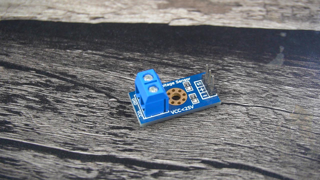
As you can see on one side we have a Terminal Block and this is where we connect the voltage and ground wires coming from a battery, a solar panel or any other voltage source. The Voltage wire is connected to the VCC terminal and the ground wire is connected to the GND terminal.
On the other side we have three male headers labeled as S, +, and -. The S pin of the sensor module is connected to the analog pin of the Arduino and the – pin is connected to the ground of the Arduino. While the + pin is not connected.
As I said earlier that using this 0-25V voltage sensor we can measure dc voltages ranging from 0.02445V to 25V DC. Now the question is how we know that the input voltage should be greater than 0.02445V.
As you know my friends,
The max Arduino analog input voltage is 5V and we know that the Arduino AVR chip has 10 bits AD “Analog to digital converter” So
5 / 1023 = 0.00489 resolution, So
0.00489 x 5 = 0.02445 volts. So
The input voltage of this module should be more than 0.02445 Volts. Let’s have a look at the circuit diagram of the voltage sensor,

It’s simply consists of two resistors connected in series, which makes a voltage divider circuit. You can clearly see the resistors values are 30K ohm and 7.5K ohm. Let’s perform calculations for this circuit.
As we already know the maximum Input voltage of this module is 25 volts dc. So
Vin = 25v
R1 = 30k ohm
R2 = 7.5k ohm
We can find out the Output voltage using the voltage divider formula which is
Vout = ( R2 x vin ) / ( R1 + R2)
Vout = (7.5 x 1000 x 25) / (30k + 7.5k)
Vout = 187500 / 37500
Vout = 5 Volts
Proteus Simulation:
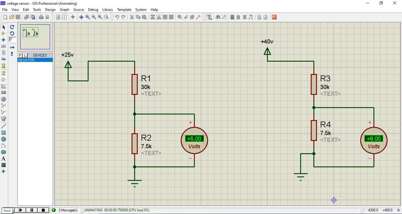
To explain how it affects the output voltage, I have designed these two circuits in Proteus simulation software. You know the voltage sensor has only two resistors which are connected in series. And you can see I am using the same value resistors.
If the voltage you are going to measure is from 0 to 25V DC then at the output you will get 5 volts which is fine.
But if you will try to measure a higher voltage, as you can see I have connected a 40 volts supply, then the output will be greater than 5 volts and it will definitely damage the Arduino Analog pin.
So with this 0-25V Voltage Sensor, you can measure a maximum of 25 volts. But, you can modify this sensor for measuring voltages even greater than 1000 volts. I will explain this in a minute. Anyway, now let’s calculate the Current using the V = IR Formula
V = IR
I = V / R
I = 25 / ( 30k + 7.5K)
I = 25 / 37.5K
I = .000666 amps
Which is equal to
I = 666 micro amps.
Interfacing Voltage Sensor with Arduino:

As usual, I am using my designed Arduino Nano development board, because it already has an Oled display module and a 5V buzzer. But it doesn’t matter if you don’t have this development board, you can do all these connections on a breadboard.
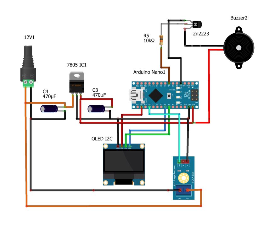
Anyway, the SSD1306 I2C Oled display module VCC and GND pins are connected to the Arduino 5V and GND pins. Whereas the SCL and SDA pins are connected to the analog pins A5 and A4. A5 is the SCL and A4 is the SDA. The same pins you can also find on the Arduino Uno, so you can also use Arduino Uno.
The 5V buzzer is connected to the Arduino Pin4. As you can see I am using a 2N2222 NPN transistor to control this Buzzer.
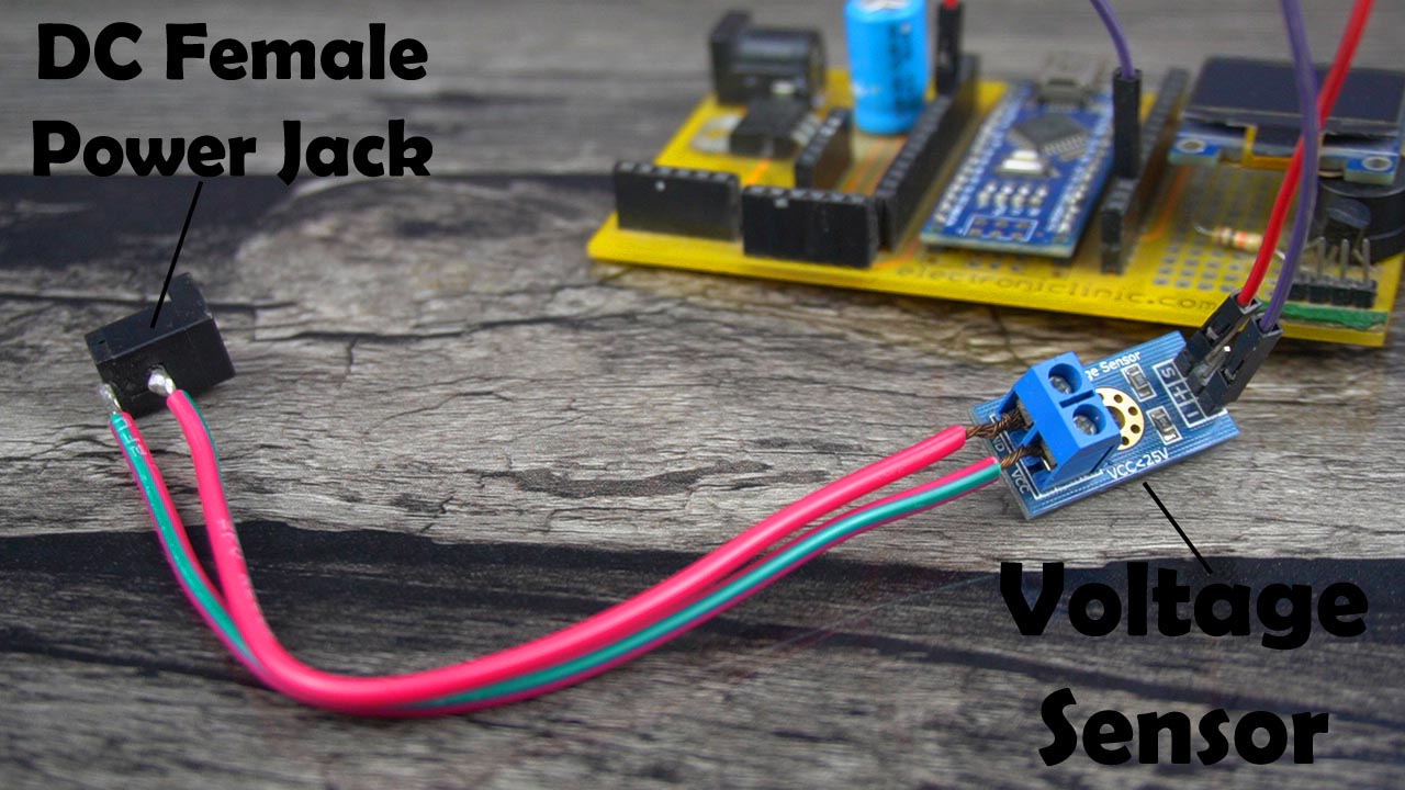
To the Voltage Sensor terminal Block, I have connected a DC female power jack. So, this way I can easily connect different voltage sources. Just make sure you connect the Positive contact or leg to the VCC terminal on the Voltage sensor and GND to the GND terminal.
The Voltage Sensor S pin is connected to the Analog pin A1 and the – pin is connected to the GND pin on the Arduino. In the circuit diagram, you can see I have connected the 12V and GND wires with the VCC and GND terminals of the voltage sensor, this way I can measure the voltage of my DC Adaptor. Or you can connect any other voltage source. So, that’s all about the connections and now, let’s go ahead and take a look at the programming.
Required Libraries:
If you are using an Oled display module then you will also need to install these two libraries. The Adafruit_GFX and the Adafruit_ssd1306.
Voltage Sensor Arduino Code:
|
1 2 3 4 5 6 7 8 9 10 11 12 13 14 15 16 17 18 19 20 21 22 23 24 25 26 27 28 29 30 31 32 33 34 35 36 37 38 39 40 41 42 43 44 45 46 47 48 49 50 51 52 53 54 |
#include <SPI.h> // include libraries #include <Wire.h> #include <Adafruit_GFX.h> #include <Adafruit_SSD1306.h> float correctionfactor = .5; int VoltageSensor = A1; float vout = 0.0; float vin = 0.0; int buzzer=4; // two resistors 30K and 7.5k ohm float R1 = 30000; // float R2 = 7500; // int value = 0; #define SCREEN_WIDTH 128 // ORelay display width, in pixels #define SCREEN_HEIGHT 64 // ORelay display height, in pixels // Declaration for an SSD1306 display connected to I2C (SDA, SCL pins) #define ORelay_RESET -1 // Reset pin # (or -1 if sharing Arduino reset pin) Adafruit_SSD1306 display(SCREEN_WIDTH, SCREEN_HEIGHT, &Wire, ORelay_RESET); void setup(){ Serial.begin(9600); pinMode(VoltageSensor, INPUT); pinMode(buzzer,OUTPUT); Serial.print("DC VOLTMETER"); display.begin(SSD1306_SWITCHCAPVCC, 0x3C); delay(2000); display.clearDisplay(); display.setTextColor(WHITE); } void loop(){ // read the value at analog input value = analogRead(VoltageSensor); vout = (value * 5.0) / 1023.0; vin = vout / (R2/(R1+R2)); vin = vin - correctionfactor; if(vin<5) { digitalWrite(buzzer,HIGH); } else { digitalWrite(buzzer,LOW); } Serial.print("INPUT V= "); Serial.println(vin,4); display.clearDisplay(); display.setCursor(10,20); display.setTextSize(3); display.setTextColor(WHITE); display.print(String(vin)+"V"); display.display(); delay(500); } |
Explanation:
|
1 |
float correctionfactor = .5; |
This is the correction factor value which is used to calibrate the voltage sensor.
|
1 |
int VoltageSensor = A1; |
The voltage sensor signal pin is connected to the analog pin A1.
|
1 |
int buzzer=4; |
The buzzer is connected to digital pin 4.
|
1 2 3 |
float R1 = 30000; // float R2 = 7500; // |
And these are the 30K and 7.5K ohms resistors.
|
1 2 3 4 5 6 7 8 9 |
#define SCREEN_WIDTH 128 // ORelay display width, in pixels #define SCREEN_HEIGHT 64 // ORelay display height, in pixels // Declaration for an SSD1306 display connected to I2C (SDA, SCL pins) #define ORelay_RESET -1 // Reset pin # (or -1 if sharing Arduino reset pin) Adafruit_SSD1306 display(SCREEN_WIDTH, SCREEN_HEIGHT, &Wire, ORelay_RESET); |
And this set of instructions is for the Oled display module.
|
1 2 3 4 5 6 7 |
value = analogRead(VoltageSensor); vout = (value * 5.0) / 1023.0; vin = vout / (R2/(R1+R2)); vin = vin - correctionfactor; |
Then in the void loop() function, we simply read the voltage sensor and calculate the input voltage coming from a battery or any other voltage source. The final value was a little off so I used the correctionfactor. Now, at this point, the vin stores the final voltage value.
Now, what you want to do with this measured voltage value; it depends on you. You can add if conditions to define different voltage levels, or you can send the measured voltage reading to your cell phone using a GSM module or a Bluetooth module. Or you can send it to an IoT cloud platform. Or you can send it through a long range LoRa network; let’s say if there is no GSM network. Just sit and think for a while what exactly you wana do with this measure value.
Anyway, in my case, just for the sake of demonstration, I am using this simple if condition.
|
1 2 3 4 5 6 7 8 9 10 11 12 13 14 15 |
if(vin<5) { digitalWrite(buzzer,HIGH); } else { digitalWrite(buzzer,LOW); } |
The Buzzer is turned ON when the voltage drops below 5.
|
1 2 3 4 5 6 7 8 9 10 11 12 13 |
display.clearDisplay(); display.setCursor(10,20); display.setTextSize(3); display.setTextColor(WHITE); display.print(String(vin)+"V"); display.display(); delay(500); |
These other instructions are used to print the voltage value on the SSD1306 Oled display module. So, that’s all about the programming. I have already uploaded this program and now let’s watch the 0-25V Voltage Sensor in Action.
Voltage Sensor Practical Demonstration:
First, I am going to start with this 12 volts adaptor.

So, I started by measuring the voltage of my 12Vdc Adaptor using a multimeter. As you can see in the image below the voltage is 12.28Vdc.

And the voltage measured with my designed voltage monitor is 12.3Vdc.

My measured value is pretty close to the multimeter value. So the first test is undoubtedly passed.
Next, I am going to measure the voltage of this 4S lithium Ion Battery pack. By the way, you can read my article on how to make your own 4S lithium Ion Battery pack for a Drone or for your upcoming projects.
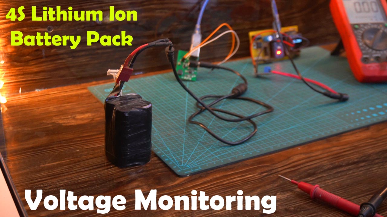
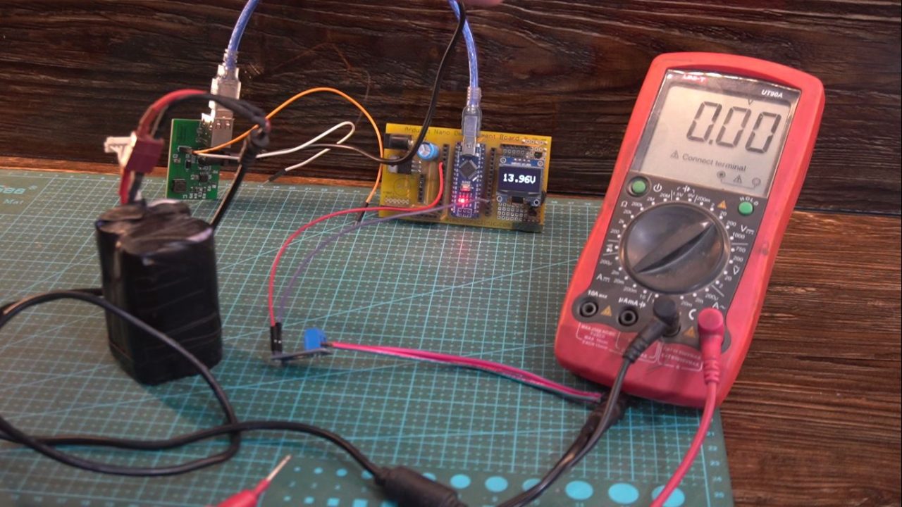
I followed the same steps, first I measure the 4S lithium Ion battery voltage using my digital multimeter. And as you can see the voltage is 13.81 volts.

The voltage measured with 0-25V Voltage sensor and Arduino is 13.96V. This is amazing.
And I also successfully measured the Voltage of a 12V Lead Acid battery. As you can see in the image below, the measure voltage is 13.05V.

And the voltage measure with my designed voltage monitor is 13.21 which is pretty close. I didn’t spent much time on the correctionfactor value. You can fine-tune this value by playing with the correctionfactor value in the programming.

For the practical demonstration, watch video tutorial given at the end of this article.
Anyway, it’s working exceptionally well.
Measuring High Voltages:
Next, I am going to explain how to modify this voltage sensor for measuring high voltages. Let’s start with 50 volts. Let’s imagine you want to measure your electric bike battery voltage.
Now the circuit will become.

As we have already calculated the current which is
I = 666 micro amps.
Input voltage Vin = Vx = 50v Dc
Module voltage = 25 volts
So using this formula we can calculate the value of Rx which is 37.5K ohms.
Vx = I Rx
Rx = ( Vx – 25) / 666 micro amps.
Rx = .037 x 1000000
Rx = 37.5K ohm.
As you can see, when the voltage is 50 volts you get exactly 5 volts at the output. So, your Arduino won’t get damaged.

So, we just build ourselves 0-50V voltage sensor.
Next, I am going to practically demonstrate how to measure AC voltages up to 320V. First, you will have to convert the AC voltage into DC.
So, if you use a resistor value of 442K ohms then you can measure 320 volts DC. So, using the same calculations you can design your own voltage sensor for measuring even high voltages.

Now, this way you can design your own voltage sensor for measuring any voltage level.

I connected these two resistors in series with the module. As I didn’t have a 442K ohm resistor so that’s why I connected a pair of 221k ohm resistors. This time I am using a dc power supply with an output voltage greater than 150 volts as you can see on the digital multimeter.
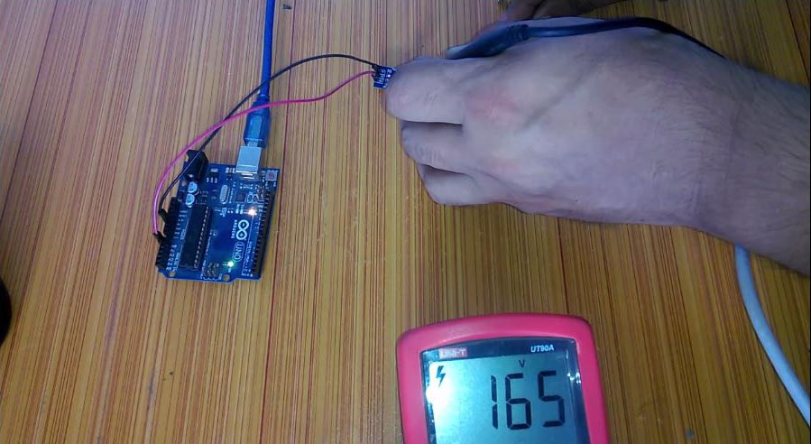
And make sure you connect a 10uf 25v capacitor across the VCC and GND terminals of the Voltage sensor. This is really important, if you don’t connect this capacitor, you won’t be able to get a stable value.
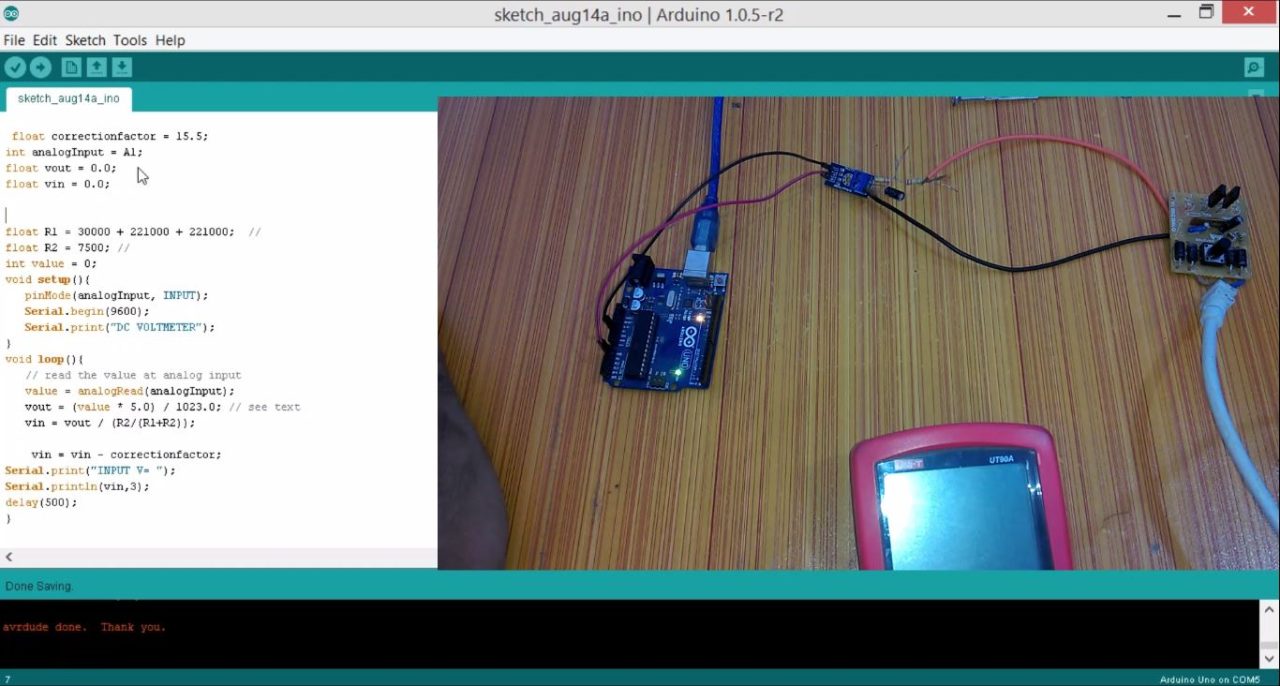
Then in the code, I made a few changes. I changed the correctionfactor value to 15.5. And I added the two resistors. As you can see I am using two resistors and each resistor is 221K ohms. And the rest of the code is exactly the same. Anyway, I uploaded this program, opened the serial monitor, and I was able to monitor the voltage source.
So, that’s all for now.
Watch Video Tutorial:

Discover more from Electronic Clinic
Subscribe to get the latest posts sent to your email.


Watch Same Video in Hindi/Urdu
https://youtu.be/SqHI1z113-I