3 Phase Transformer Load Monitoring using Arduino, ACS712 and VB.net
Table of Contents
3 Phase Transformer, Project Description:
In this tutorial, you will learn how to make a 3 phase transformer prototype model and monitor the load on each phase using a computer application designed in a visual basic dot net, which is also known as vb.net. The load on each phase is measured using the ACS712 Current sensor, and the final calculated values are sent serially to the computer application using Arduino. Due to the unavailability of the 3 phase transformer, I will make my own 3 phase transformer prototype using 3 single-phase transformers. The designed project can be used with the real 3 phase transformer without any problem. The load on 3 phases “Red, Yellow, and Blue” of the Transformer is monitored using the ACS712 current sensors.
This tutorial covers
- Soldering
- ACS712 current sensors Interfacing with Arduino
- Load monitoring Arduino programming
- net Programming and finally
- Testing
Note: for the step-by-step project explanation you can watch the video Tutorial given at the End of this Article.
Cautions: This project makes use of the 220/230 Vac Supply. Make sure you use the Protection Gloves. If you are a beginner then ask someone who has complete command on Electronics. Don’t touch any wires while the Transformers are turned ON.
Amazon Links:
Other Tools and Components:
Super Starter kit for Beginners
PCB small portable drill machines
DISCLAIMER:
Please Note: these are affiliate links. I may make a commission if you buy the components through these links. I would appreciate your support in this way!
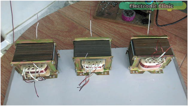
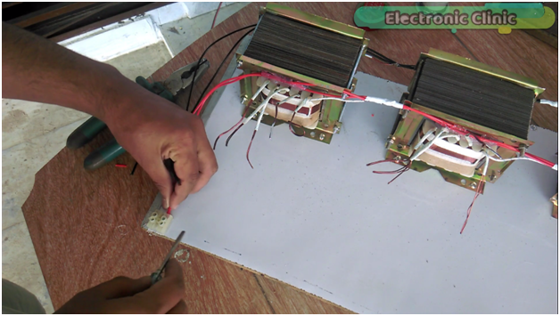
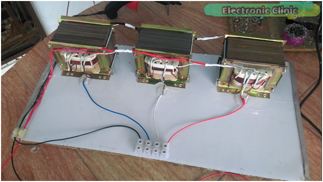
These are the 3 transformers fixed on the hard board and as you can see all the transformers has different loops.
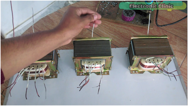
These three wires are the neutral wires and will be connected together.
while these three wires are the input live wires and will also be connected together.
Then we will check the voltage on all the loops, and select the ones which has 220 or 230 volts, which will be then used as the Red , Yellow, and Blue phases for the demonstration purposes.
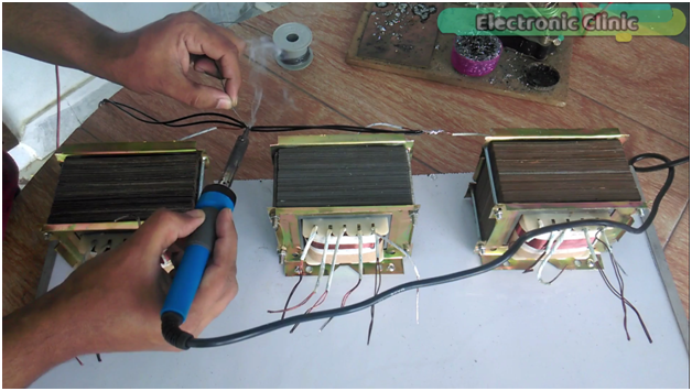
For the easy soldering first remove thin layer of insulation.
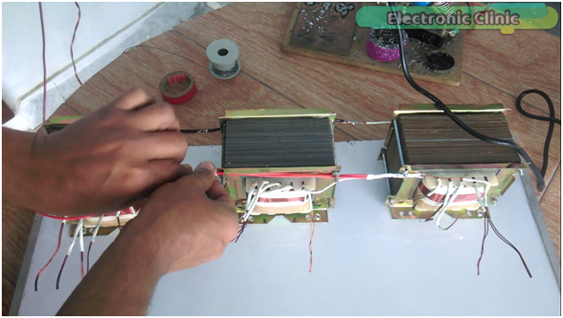
Connect the neutral wires together.
Now we will connect the input live wires together, after all the wires are connected together then use the insulation tape, and make sure there is no bare wire.Connect the live and neutral wires with the pvc strip connector
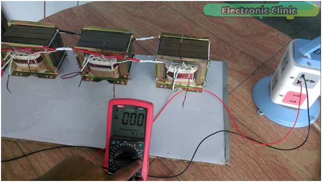
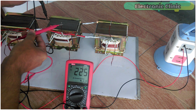
The meter is set on 750 volts ac.
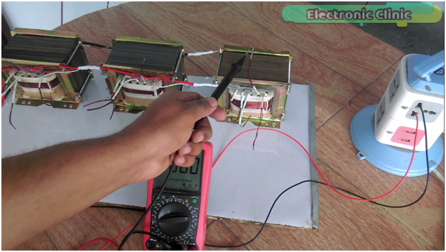
Don’t touch these wires when the transformers are turned ON.
Connect one test lead with the neutral and connect the other test lead with the output.
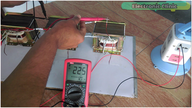
As you can see all the three phases has 225 volts. we are done with the testing and all the transformers are working.
We will be using only these three loops as the 3 phases, Red, Yellow, and Blue. I Soldered three wires and connected these wires with the PVC Strip connector. our three phase transformer prototype model is ready and can be used to power up some loads. Now let’s start working on the current sensors and Arduino.
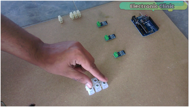
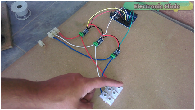
First of all fix all the components on the hard board, and then connect the PVC Strip connectors with the ACS712 current sensors as you can see in the picture below.
Connect the ground pins of all the current sensors together and then connect it with the Arduino’s ground.
Now connect the VCC pins of all the current sensors together and then connect it with the Arduino’s 5v.
Connect the output pins of all the current sensors with the Arduino’s Analog pins A1, A2 and A3.
All the connections are done.
I will connect three hundred watt bulbs over here for the demonstration purposes and monitor the load on the computer screen using a computer application designed in VB.net. Now let’s discuss the Arduino Programming.
3 Phase Transformer Load Monitoring Arduino Programming:
This is the same program which I used in my previous project based on the over load monitoring and protection system.
Over load monitoring and Protection using Arduino & ACS712 Current sensor
As this project is based on three phase load monitoring system and this time I am using three current sensors, so I defined pins for two more current sensors…
Three current sensors are connected with the analog pins 1, 2 and 3…
Defined three variables of the type string for storing the RMS values…
Created a user defined function with the name RYB and added all the RMS values together using comma as the delimiter and then the complete message is sent to the computer application using the serial.println function…
while rest of the program remains the same
|
1 2 3 4 5 6 7 8 9 10 11 12 13 14 15 16 17 18 19 20 21 22 23 24 25 26 27 28 29 30 31 32 33 34 35 36 37 38 39 40 41 42 43 44 45 46 47 48 49 50 51 52 53 54 55 56 57 58 59 60 61 62 63 64 65 66 67 68 69 70 71 72 73 74 75 76 77 78 79 80 81 82 83 84 85 86 87 88 89 90 91 92 93 |
#include <stdlib.h> String textForSMS; char buff[10]; const unsigned long sampleTime = 100000UL; // sample over 100ms, it is an exact number of cycles for both 50Hz and 60Hz mains const unsigned long numSamples = 250UL; // choose the number of samples to divide sampleTime exactly, but low enough for the ADC to keep up const unsigned long sampleInterval = sampleTime/numSamples; // the sampling interval, must be longer than then ADC conversion time const int adc_zero = 510; // Red line const int currentPin = 1; // current sensor connected here analog pin A1 float rms; // Yellow line const int currentPin2 = 2; // analog pin A2 float rms2; // Blue Line const int currentPin3 = 3; // analog pin A3 float rms3; String stringrms; String stringrms2; String stringrms3; void setup() { Serial.begin(9600); pinMode(currentPin, INPUT); pinMode(currentPin2, INPUT); pinMode(currentPin3, INPUT); } void loop() { RYB(); // red yellow blue lines checking, its a calling function. textForSMS = textForSMS + stringrms + "," + stringrms2 + "," + stringrms3 +","; Serial.println(textForSMS); delay(1000); textForSMS = ""; } void RYB() // red , yellow , blue lines { unsigned long currentAcc = 0; unsigned int count = 0; unsigned long currentAcc2 = 0; unsigned long currentAcc3 = 0; unsigned long prevMicros = micros() - sampleInterval ; while (count < numSamples) { if (micros() - prevMicros >= sampleInterval) { int adc_raw = analogRead(currentPin) - adc_zero; // user 1 currentAcc += (unsigned long)(adc_raw * adc_raw); // user 1 int adc_raw2 = analogRead(currentPin2) - adc_zero; // user2 currentAcc2 += (unsigned long)(adc_raw2 * adc_raw2); // user 2 int adc_raw3 = analogRead(currentPin3) - adc_zero; // illegal user currentAcc3 += (unsigned long)(adc_raw3 * adc_raw3); // illegal user ++count; prevMicros += sampleInterval; } } rms = sqrt((float)currentAcc/(float)numSamples) * (75.7576 / 1024.0); delay(100); rms2 = sqrt((float)currentAcc2/(float)numSamples) * (75.7576 / 1024.0); delay(100); rms3 = sqrt((float)currentAcc3/(float)numSamples) * (75.7576 / 1024.0); delay(100); stringrms = dtostrf(rms, 1, 4, buff); stringrms2 = dtostrf(rms2, 1, 4, buff); stringrms3 = dtostrf(rms3, 1, 4, buff); //Serial.println("\n"); delay(1000); //Serial.println(currentAcc); // delay(1000); } |
3 Phase Transformer Load Monitoring VB.net Application Programming:
I have used vb.net with Arduino in so many other projects, and also I have some getting started tutorials on vb.net in which I explained how to add text boxes, labels , timers etc and how to do serial communication. You can check out the playlist on my YouTube channel “Electronic Clinic” by clicking on the link below:
Desktop Applications Designing Playlist:
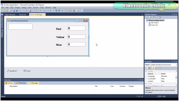
As you can see this application as few components
4 text boxes, with names textbox1, textbox2, textbox3, and textbox4.
Three labels, red, yellow and blue.
A serial port and a timer.
The timer interval is set to 3000 milli seconds, which are equal to 3 seconds.
To open the coding double click on the form.
We start by importing the system.io and system.io.port…
this code is for the serial port, 32 is the port number on which the Arduino is installed while 9600 is the baud rate, the same baud rate should be used on the Arduino side, otherwise the communication will not work.
This code is executed every three seconds and the purpose of this code is to split the entire message and display the values in text boxes labeled with red, yellow, and blue.
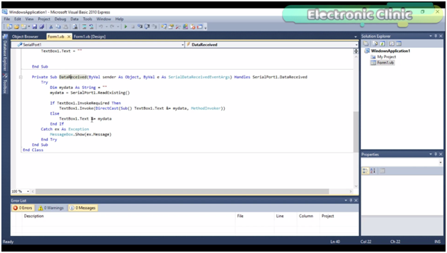
While the datareceived function is used to receive the data from Arduino. I have already explained this function in my previous tutorials. Check my playlist on desktop applications designing. So that’s it..
Vb.net application Programming:
|
1 2 3 4 5 6 7 8 9 10 11 12 13 14 15 16 17 18 19 20 21 22 23 24 25 26 27 28 29 30 31 32 33 34 35 36 37 38 39 40 41 42 43 44 45 46 47 48 49 50 51 52 53 54 |
Imports System.IO Imports System.IO.Ports Public Class Form1 Dim value1 As Integer Private Sub Form1_Load(ByVal sender As System.Object, ByVal e As System.EventArgs) Handles MyBase.Load SerialPort1.Close() SerialPort1.PortName = "com32" SerialPort1.BaudRate = "9600" SerialPort1.DataBits = 8 SerialPort1.Parity = Parity.None SerialPort1.StopBits = StopBits.One SerialPort1.Handshake = Handshake.None SerialPort1.Encoding = System.Text.Encoding.Default SerialPort1.Open() End Sub Private Sub Timer1_Tick(ByVal sender As System.Object, ByVal e As System.EventArgs) Handles Timer1.Tick Dim s As String s = TextBox1.Text + "," + "," + "," + "," Dim somestring() As String ' Split string based on comma somestring = s.Split(New Char() {","c}) TextBox2.Text = somestring(0) ' value1 = Convert.ToDecimal(TextBox2.Text) TextBox3.Text = somestring(1) TextBox4.Text = somestring(2) TextBox1.Text = "" End Sub Private Sub DataReceived(ByVal sender As Object, ByVal e As SerialDataReceivedEventArgs) Handles SerialPort1.DataReceived Try Dim mydata As String = "" mydata = SerialPort1.ReadExisting() If TextBox1.InvokeRequired Then TextBox1.Invoke(DirectCast(Sub() TextBox1.Text &= mydata, MethodInvoker)) Else TextBox1.Text &= mydata End If Catch ex As Exception MessageBox.Show(ex.Message) End Try End Sub End Class |
For the Practical Demonstration watch the following video.









Fahad Bhai What is the rating of the transformers you have used in this project ?
brother ratings really doesn’t matter. select any transformers with different tapings.
What is your whatsapp number