AD9833 Programmable Waveform Generator using Arduino
Last Updated on August 17, 2024 by Engr. Shahzada Fahad
Table of Contents
AD9833 Programmable waveform generator:
In this article, we will discuss about the AD9833 programmable waveform generator and we will be interfacing it with the Arduino Nano. The AD9833 is a low power, programmable waveform generator capable of producing sine, triangular, and square wave outputs. Waveform generation is required in various types of sensing, actuation, and time domain reflectometry (TDR) applications. The output frequency and phase are software programmable, allowing easy tuning. No external components are needed. The frequency registers are 28 bits wide: with a 25 MHz clock rate, resolution of 0.1 Hz can be achieved; with a 1 MHz clock rate, the AD9833 can be tuned to 0.004 Hz resolution.
The AD9833 can output sinusoidal, triangular, and square waveforms. The AD9833 can output sine, triangular, and square waveforms up to a frequency of 12.5 megahertz. It is interfaced with a microcontroller using three wires SPI. It can be supplied with dc voltage ranging between 2.3 and 5.5 volts and too lower, the power consumption there is an option where you can power down the module. Due to wide input voltge range the AD9833 programmable wafeform generator can also be used with 3.3v compatible controller boards like ESP32 and Nodemcu ESP8266, etc. But for the easy understanding we are going to use it with the Arduino Nano. You can also use other boards of the arduino family like e.g. Arduino Uno, Arduino Mega, etc.
Amazon link:
Arduino Nano USB-C Type (Recommended)
*Please Note: These are affiliate links. I may make a commission if you buy the components through these links. I would appreciate your support in this way!
AD9833 interfacing with Arduino, Circuit diagram:
A circuit diagram of the implemented system is shown here.
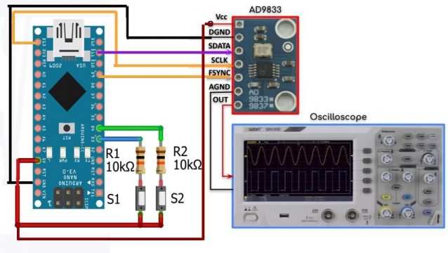
We have the AD9833 module connected with the Arduino using SPI bus, where the serial data line (SDATA) pin is connected to master output to slave input line of the Arduino which is pin D11. The serial clock is connected to the clock pin of Arduino which is D13 and the FSYNC is connected to chip select which is pin D9. We also have the analog output from the module connected to a scope we have a 2-bit dip switch which is connected to pins D3 and D4 of the arduino that act as a signal selector. So according to this truth table here.
0 0 gives us a sinusoid
0 1 triangular wave
1 0 square wave
1 1 gives us a square wave with half the frequency.
We also have a 10k part connected to analog line A6 which controls the frequency of the output waveform.
AD9833 Arduino Complete code:
|
1 2 3 4 5 6 7 8 9 10 11 12 13 14 15 16 17 18 19 20 21 22 23 24 25 26 |
//======================== //AD9833 Signal Generator //======================== #include<AD9833.h> //---------------------------- AD9833 gen(9); long f; int sw1, sw2; //======================================== void setup() { pinMode(3,INPUT); pinMode(4,INPUT); gen.Begin(); gen.EnableOutput(true); } //======================================== void loop() { f = map(analogRead(A6),0,1023,1000,5000); sw1 = digitalRead(4); sw2 = digitalRead(3); if(sw1==LOW && sw2==LOW) gen.ApplySignal(SINE_WAVE,REG0,f); if(sw1==LOW && sw2==HIGH) gen.ApplySignal(TRIANGLE_WAVE,REG0,f); if(sw1==HIGH && sw2==LOW) gen.ApplySignal(SQUARE_WAVE,REG0,f); if(sw1==HIGH && sw2==HIGH) gen.ApplySignal(HALF_SQUARE_WAVE,REG0,f); } |
AD9833 Arduino Code Explanation:
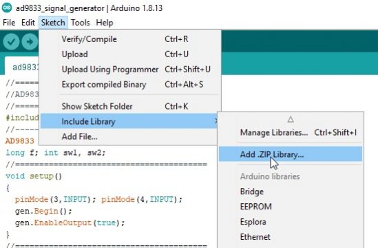
First of all we need to include the library AD9833 so first we will go to the sketch and click on the add zip library.
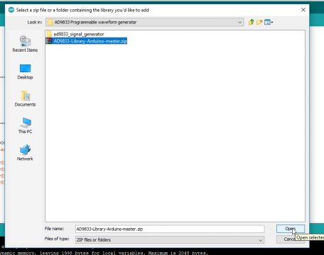
Now download the library for AD9833 and insert the library.
Now include the library
|
1 |
#include<AD9833.h> |
So we can access the AD9833 module we declare this object which is connected to digital pin D9 within the setup function.
|
1 |
AD9833 gen(9); |
We initialize the object and we enable the output of the module inside the loop function and via a 10k pot we read the analog input connected to A6 and then ramp the values between 1000 and 5000. Now this will represent our frequency range and the module can support frequencies up to 12.5 megahertz. Next we read the status of switch 1 and switch 2 which are connected to pins 3 and 4 of the Arduino and based on their values.
|
1 2 3 4 5 6 7 8 9 10 11 |
void setup() { pinMode(3,INPUT); pinMode(4,INPUT); gen.Begin(); gen.EnableOutput(true); } |
We either display a sinusoid or a triangular waveform or a square wave or a square wave at half the frequency and now for a quick demonstration with the dip switch positions at 0 0 we get a sinusoid and we can increase the frequency between 1 kilohertz up to 5 kilohertz for a switch value of 0 1 we get a triangular waveform setting the switches to 1 0 gives us a square waveform and finally for a switch position of 1 1 we get a square wave with half the frequency.
|
1 2 3 4 5 6 7 8 9 10 11 12 13 14 15 16 17 18 19 20 |
void loop() { f = map(analogRead(A6),0,1023,1000,5000); sw1 = digitalRead(4); sw2 = digitalRead(3); if(sw1==LOW && sw2==LOW) gen.ApplySignal(SINE_WAVE,REG0,f); if(sw1==LOW && sw2==HIGH) gen.ApplySignal(TRIANGLE_WAVE,REG0,f); if(sw1==HIGH && sw2==LOW) gen.ApplySignal(SQUARE_WAVE,REG0,f); if(sw1==HIGH && sw2==HIGH) gen.ApplySignal(HALF_SQUARE_WAVE,REG0,f); } |
AD9833 Programmable Waveform Generator with seven segment display and MAX 7219:
The AD9833 programmable waveform generator project is modified. The waveform frequency is now displayed on a seven segment screen controlled by a max7219 driver. A modified circuit diagram of the implemented project is shown here.
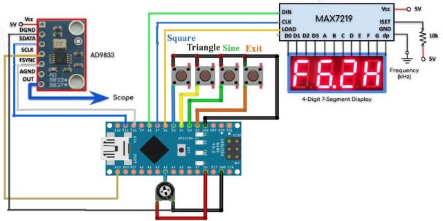
We now have the frequency of the waveform displayed on a four digit seven segment display which is controlled by the max7219 driver. The max7219 is serially interfaced with the Arduino using three digital pins where the load clock and data in are connected to pins six, seven and eight of the Arduino. We also have three push buttons connected to three digital pins of the Arduino when we press any of these buttons the selected waveform will be displayed on the scope and the waveform frequency in kilohertz will be displayed on the four digits seven segment display. Finally we have this push button which is connected to interrupt pin 0 when pressed will cause the selected waveform to exit and the main menu title is shown on the seven segment display.
Waveform Generator Arduino Complete Code:
|
1 2 3 4 5 6 7 8 9 10 11 12 13 14 15 16 17 18 19 20 21 22 23 24 25 26 27 28 29 30 31 32 33 34 35 36 37 38 39 40 41 42 43 44 45 46 47 48 49 50 51 52 53 54 55 56 57 58 59 60 61 62 63 64 65 66 67 68 69 70 71 72 73 74 75 76 77 78 79 80 81 82 83 84 85 86 87 88 89 90 91 92 93 |
#include <AD9833.h> #include "LedControl.h" AD9833 gen(10); LedControl disp = LedControl(7,8,6,1); long f; int d0, d1, sw; volatile bool exitWaveform; void setup() { pinMode(3,INPUT); pinMode(4,INPUT); pinMode(5,INPUT); // pinMode(A6,OUTPUT); gen.Begin(); gen.EnableOutput(true); disp.shutdown(0,false); disp.setIntensity(0,15); disp.clearDisplay(0); attachInterrupt(0,ISR_exit,RISING); } void loop() { exitWaveform = false; disp.setChar(0,0,'H',false); disp.setChar(0,1,'E',false); disp.setChar(0,2,'L',false); disp.setChar(0,3,'P',false); if(digitalRead(3) == HIGH) sineWaveform(); if(digitalRead(4) == HIGH) triangleWaveform(); if(digitalRead(5) == HIGH) squareWaveform(); } void sineWaveform() { while(1) { if(exitWaveform == true) return; f = map(analogRead(A6),0,1023,1000,9999); d0=f/1000; d1=(f/100)%10; disp.setChar(0,0,'F',false); disp.setDigit(0,1,d0,true); disp.setDigit(0,2,d1,false); disp.setChar(0,3,'H',false); delay(200); gen.ApplySignal(SINE_WAVE,REG0,f); } } void triangleWaveform() { while(1) { if(exitWaveform == true) return; f = map(analogRead(A6),0,1023,1000,9999); d0=f/1000; d1=(f/100)%10; disp.setChar(0,0,'F',false); disp.setDigit(0,1,d0,true); disp.setDigit(0,2,d1,false); disp.setChar(0,3,'H',false); delay(200); gen.ApplySignal(TRIANGLE_WAVE,REG0,f); } } void squareWaveform() { while(1) { if(exitWaveform == true) return; f = map(analogRead(A6),0,1023,1000,9999); d0=f/1000; d1=(f/100)%10; disp.setChar(0,0,'F',false); disp.setDigit(0,1,d0,true); disp.setDigit(0,2,d1,false); disp.setChar(0,3,'H',false); delay(200); gen.ApplySignal(SQUARE_WAVE,REG0,f); } } //======================================================= void ISR_exit() { exitWaveform = true; } |
Programmable Waveform Arduino Code Explanation:
First we need to include these two libraries one for the ad9833 and the other for the max7219 ic which are already discussed above.
|
1 2 3 4 5 6 7 |
#include <AD9833.h> #include "LedControl.h" Now we will declare object for the ad9833 AD9833 gen(10); |
The object for the max7219ic which interface with the Arduino as follows; the dn is connected to pin 7, clock to pin 8, load to pin 6. This argument here indicates that we have only one ic of the max7219
In the setup function we first declare that the pin number 3, 4 and 5 will be used as input.
|
1 2 3 4 5 |
pinMode(3,INPUT); pinMode(4,INPUT); pinMode(5,INPUT); |
Then we initializethe ad9833 module and clear the seven segment display and set its intensity.
|
1 2 3 4 5 6 7 8 9 10 11 12 13 14 |
gen.Begin(); gen.EnableOutput(true); disp.shutdown(0,false); disp.setIntensity(0,15); disp.clearDisplay(0); attachInterrupt(0,ISR_exit,RISING); |
Inside the loop function we display these characters on the seven segment display and while the program is looping if the sine switch is pressed for which we are using push button connected to the digital pin 3 then we will call function sineWaveform().
|
1 2 3 4 5 6 7 8 9 10 11 |
exitWaveform = false; disp.setChar(0,0,'H',false); disp.setChar(0,1,'E',false); disp.setChar(0,2,'L',false); disp.setChar(0,3,'P',false); if(digitalRead(3) == HIGH) sineWaveform(); |
If the triangle switch is pressed for which we are using push button connected to the digital pin 4 of the Arduino then we call this function triangleWaveform().
|
1 |
if(digitalRead(4) == HIGH) triangleWaveform(); |
Similarly, if the square wave switch is pressed for which we are using push button connected to the digital pin 5 then we call the squareWaveform();.
|
1 |
if(digitalRead(5) == HIGH) squareWaveform(); |
Pressing the sine button will execute this function where we will get the variable frequency from the potentiometer and this would be the range of the frequency then we would display the frequency on the seven segment display and then we will send the sine wave form to the analog output of the ad9833 module.This while loop will loop indefinitely until we press the interrupt button and the program jumps to the interrupt service routine.
|
1 2 3 4 5 6 7 8 9 10 11 12 13 14 15 16 17 18 19 20 21 22 23 24 25 26 27 28 29 30 31 32 33 |
Void sineWaveform() { while(1) { if(exitWaveform == true) return; f = map(analogRead(A6),0,1023,1000,9999); d0=f/1000; d1=(f/100)%10; disp.setChar(0,0,'F',false); disp.setDigit(0,1,d0,true); disp.setDigit(0,2,d1,false); disp.setChar(0,3,'H',false); delay(200); gen.ApplySignal(SINE_WAVE,REG0,f); } } |
Where the value of this boolean variable will become true and then when we come back to the function sineWaveform() this if statement becomes true forcing the program to exit the function and return to the main loop function. The same procedures apply to function triangleWaveform() and function squareWaveform().
Applications:
- Frequency stimulus/waveform generation
- Liquid and gas flow measurement
- Sensory applications: proximity, motion, and defect detection
- Line loss/attenuation Test and medical equipment
- Sweep/clock generators
- Time domain reflectometry (TDR) applications
Discover more from Electronic Clinic
Subscribe to get the latest posts sent to your email.


What would be the flag setting for an up ramp signal ?
Do you have a ling to the LedControl library you used for this project?
Is it necessary to have FSYNC if there is only one 9833 module? can we leave it pulled down or up whichever the case?