Android HMI development- control HMI touch screen using Bluetooth “TFT touch screen”
Last Updated on August 18, 2024 by Engr. Shahzada Fahad
Table of Contents
Android HMI Development, Description:
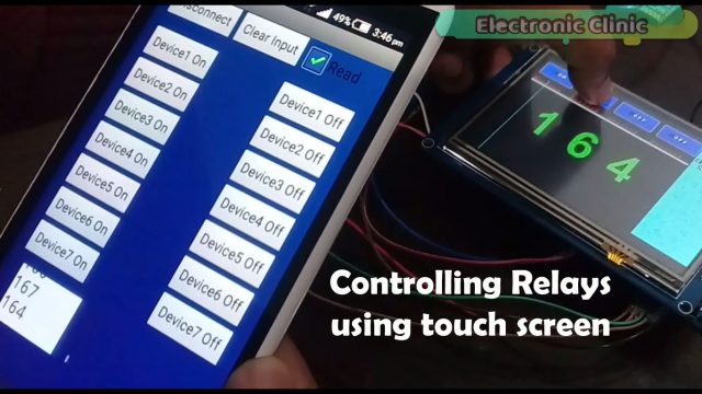
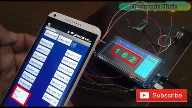
Android HMI development– In this tutorial, you will learn how to control a 5 inch TFT HMI touch screen wirelessly using the Hc-05 or Hc-06 Bluetooth module and an android cell phone. This is a dual control system, the relays can be controlled using the HMI touch screen and can also be controlled using your android cell phone.
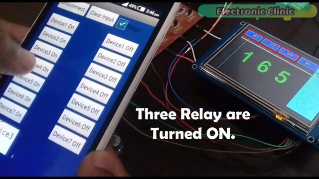
Any load which is turned on using the HMI touch screen can be turned off using the cell phone application, and any load which is turned on using the android cell phone application can also be turned off using the HMI TFT touch screen.
With the help of this project “Android HMI development” you can also monitor the sensor values on the screen and also in the application.
Android HMI development project is entirely based on my previous three tutorials. In first tutorial, I created one button to control an led and display the on time of a controller in seconds. In this tutorial I covered all the basic functions.
In the second tutorial, I converted two images and then displayed those images on the LCD. This tutorial is really important and explains how Pictures can be displayed on the HMI TFT touch screen.
While in the third tutorial I combined the techniques used in the first two tutorials, the sensor values as you can see on the screen are actually the images which I converted; in the second tutorial, I explained the image conversion in very detail.
So I highly recommend before you start working on the Android HMI development project you should watch my previous three tutorials otherwise you won’t be able to make this project. For the detailed discussion and explanation watch video tutorial given at the end. Without any further delay, let’s get started!!!
Amazon links:
ITDB02 Arduino mega shield 2.1:
*Disclosure: These are affiliate links. As an Amazon Associate I earn from qualifying purchases.
This Android HMI development Project is the modified version of the project which I explained in third tutorial. As you can see the GUI application is exactly the same, I am using the same relay module and the same variable resistor. In this project I made only three changes.
- I added a Bluetooth module with serial port 3.if you don’t know how to use the hc-05 or hc-06 Bluetooth module, then you should watch my getting started tutorial on how to use the Bluetooth module, in which I explained everything in very detail, like for example, how to change the name of the Bluetooth module, how to change the pin code or password etc. You can find this in the related projects section given at the end.
- I made a very little change in the controller programming, so that I can communicate with the HMI touch screen using my android cell phone. So in this project I will not explain the entire program, because I have already explained this program in my third tutorial on HMI touch screen. But I will explain the changes which I made.
- I fixed all the components on the hard board.
Circuit Diagram of Android HMI:
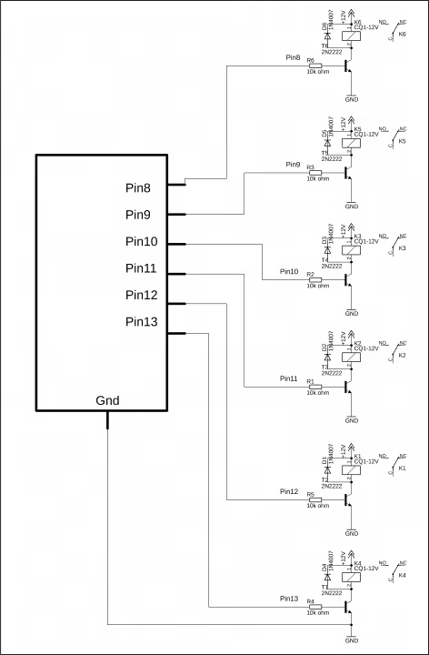
This is the circuit diagram of the relay module, if in case you want to make your own Relay module; otherwise you can purchase a readymade relay Module, Rest of the connections are already explained in my previous tutorials. Watch all the three tutorials given above.
Programming of the HMI Touch Screen:
|
1 2 3 4 5 6 7 8 9 10 11 12 13 14 15 16 17 18 19 20 21 22 23 24 25 26 27 28 29 30 31 32 33 34 35 36 37 38 39 40 41 42 43 44 45 46 47 48 49 50 51 52 53 54 55 56 57 58 59 60 61 62 63 64 65 66 67 68 69 70 71 72 73 74 75 76 77 78 79 80 81 82 83 84 85 86 87 88 89 90 91 92 93 94 95 96 97 98 99 100 101 102 103 104 105 106 107 108 109 110 111 112 113 114 115 116 117 118 119 120 121 122 123 124 125 126 127 128 129 130 131 132 133 134 135 136 137 138 139 140 141 142 143 144 145 146 147 148 149 150 151 152 153 154 155 156 157 158 159 160 161 162 163 164 165 166 167 168 169 170 171 172 173 174 175 176 177 178 179 180 181 182 183 184 185 186 187 188 189 190 191 192 193 194 195 196 197 198 199 200 201 202 203 204 205 206 207 208 209 210 211 212 213 214 215 216 217 218 219 220 221 222 223 224 225 226 227 228 229 230 231 232 233 234 235 236 237 238 239 240 241 242 243 244 245 246 247 248 249 250 251 252 253 254 255 256 257 258 259 260 261 262 263 264 265 266 267 268 269 270 271 272 273 274 275 276 277 278 279 280 281 282 283 284 285 286 287 288 289 290 291 292 293 294 295 296 297 298 299 300 301 302 303 304 305 306 307 308 309 310 311 312 313 314 315 316 317 318 319 320 321 322 323 324 325 326 327 328 329 330 331 332 333 334 335 336 337 338 339 340 341 342 343 344 345 346 347 348 349 350 351 352 353 354 355 356 357 358 359 360 361 362 363 364 365 366 367 368 369 370 371 372 373 374 375 376 377 378 379 380 381 382 383 384 385 386 387 388 389 390 391 392 393 394 395 396 397 398 399 400 401 402 403 404 405 406 407 408 409 410 411 412 413 414 415 416 417 418 419 420 421 422 423 424 425 426 427 428 429 430 431 432 433 434 435 436 437 438 439 440 441 442 443 444 445 446 447 448 449 450 451 452 453 454 455 456 457 458 459 460 461 462 463 464 465 466 467 468 469 470 471 472 473 474 475 476 477 478 479 480 481 482 483 484 485 486 487 488 489 490 491 492 493 494 495 496 497 498 499 500 501 502 503 504 505 506 507 508 509 510 511 512 513 514 515 516 517 518 519 520 521 522 523 524 525 526 527 528 529 530 531 532 533 534 535 536 537 538 539 540 541 542 543 544 545 546 547 548 549 550 551 552 553 554 555 556 557 558 559 560 561 562 563 564 565 566 567 568 569 570 571 572 573 574 575 576 577 578 579 580 581 582 583 584 585 586 587 588 589 590 591 592 593 594 595 596 597 598 599 600 601 602 603 604 605 606 607 608 609 610 611 612 613 614 615 616 617 618 619 620 621 622 623 624 625 626 627 628 629 630 631 632 633 634 635 636 637 638 639 640 641 642 643 644 645 646 647 648 649 650 651 652 653 654 655 656 657 658 659 660 661 662 663 664 665 666 667 668 669 670 671 672 673 674 675 676 677 678 679 680 681 682 683 684 685 686 687 688 689 690 691 692 693 694 695 696 697 698 699 700 701 702 703 704 705 706 707 708 709 710 711 712 713 714 715 716 717 718 719 720 721 |
#include <UTouch.h> #include <UTouchCD.h> #define TOUCH_ORIENTATION LANDSCAPE #include <UTFT_Buttons.h> #include <UTFT.h> #include <avr/pgmspace.h> #include <SoftwareSerial.h> long int bdata; extern uint8_t SmallFont[]; extern uint8_t BigFont[]; extern uint8_t SevenSegNumFont[]; int button1on = 0; // this will be used as a flag for button1 int button2on = 0;// this will be used as a flag for button2 and so on int button3on = 0; int button4on = 0; int alert1 = 0; // this will be used as a flag int relay1 = 13; int relay2 = 12; int relay3 = 11; int relay4 = 10; int sensor1 = A1; // Sensor connected with A0 of the Mega int x, y; char stCurrent[20]=""; int stCurrentLen=0; char stLast[20]=""; int bg[] = { 0, 0, 255}; int fg[] = { 255, 255, 255}; UTFT myGLCD(ITDB50, 38,39,40,41); // Remember to change the model parameter to suit your display module! UTouch myTouch(6,5,4,3,2); extern unsigned int a0[0x76C]; extern unsigned int a1[0x76C]; extern unsigned int a2[0x76C]; extern unsigned int a3[0x76C]; extern unsigned int a4[0x76C]; extern unsigned int a5[0x76C]; extern unsigned int a6[0x76C]; extern unsigned int a7[0x76C]; extern unsigned int a8[0x76C]; extern unsigned int a9[0x76C]; int scale = 3; // for the pic size to make it large or small // for specifying the upper left x coordinates and y coordinates for buttons. // as the buttons will be displayed in the same row so the x values will be different and the y values will be the same. int imagex = 100; //for digit1 int imagey = 200; // for digit1 int imagex2 = 250; // for digit 2 int imagey2 = 200; // for digit2 int imagex3 = 400;// for digit 3 int imagey3 = 200;// for digit 3 // for button1 int button1x1 = 10; // 90 int button1y1 = 20; // 180 int button1x2 = 140; // 220 int button1y2 = 80; // 230 // for button2 int button2x1 = 160; // 160 int button2y1 = 20; // 20 int button2x2 = 290; // 290 int button2y2 = 80; // 80 // for button3 int button3x1 = 310; // 310 int button3y1 = 20; // 20 int button3x2 = 450; // 450 int button3y2 = 80; // 80 // for button4 int button4x1 = 470; // 160 int button4y1 = 20; // 20 int button4x2 = 610; // 290 int button4y2 = 80; // 80 int data1 = 0; // new code // on off codes for device1 long int password1 = 555;// to on long int password2 = 551;// to off //device2 long int password3 = 777; // TO TURN ON long int password31 = 222; // to turn off //device3 long int password4 = 221; // to turn on long int password41 = 444; // to turn off //device4 long int password5 = 441; // to turn on long int password51 = 888; // to turn off // new code end // Finally we set up UTFT_Buttons :) void drawButtons() { // Draw the upper row of buttons myGLCD.setColor(bg[0], bg[1], bg[2]); myGLCD.fillRoundRect (button1x1, button1y1, button1x2, button1y2); myGLCD.setColor(fg[0], fg[1], fg[2]); myGLCD.drawRoundRect (button1x1, button1y1, button1x2, button1y2); myGLCD.print(" ON", 50, 40); // 115, 195 myGLCD.setBackColor (0, 0, 255); // button2 codding myGLCD.setColor(bg[0], bg[1], bg[2]); myGLCD.fillRoundRect (button2x1, button2y1, button2x2, button2y2); myGLCD.setColor(fg[0], fg[1], fg[2]); myGLCD.drawRoundRect (button2x1, button2y1, button2x2, button2y2); myGLCD.print(" ON", 200, 40); // 115, 195 myGLCD.setBackColor (0, 0, 255); // button3 codding myGLCD.setColor(bg[0], bg[1], bg[2]); myGLCD.fillRoundRect (button3x1, button3y1, button3x2, button3y2); myGLCD.setColor(fg[0], fg[1], fg[2]); myGLCD.drawRoundRect (button3x1, button3y1, button3x2, button3y2); myGLCD.print(" ON", 350, 40); // 115, 195 myGLCD.setBackColor (0, 0, 255); // button4 codding myGLCD.setColor(bg[0], bg[1], bg[2]); myGLCD.fillRoundRect (button4x1, button4y1, button4x2, button4y2); myGLCD.setColor(fg[0], fg[1], fg[2]); myGLCD.drawRoundRect (button4x1, button4y1, button4x2, button4y2); myGLCD.print(" ON", 500, 40); // 115, 195 myGLCD.setBackColor (0, 0, 255); myGLCD.setColor(fg[1], fg[3], fg[6]); myGLCD.setBackColor (0, 0, 0); myGLCD.print("Device1", 10, 100); myGLCD.print("Device2", 160, 100); myGLCD.print("Device3", 310, 100); myGLCD.print("Device4", 470, 100); // for line myGLCD.drawRect(10, 120, 610, 124); myGLCD.setColor(fg[0], fg[1], fg[2]); // white myGLCD.fillRect(10, 120, 610, 124); // for large rectangle myGLCD.drawRect(10, 130, 610, 450); myGLCD.setColor(fg[255], fg[255], fg[255]); myGLCD.fillRect(10, 130, 610, 450); // for right side rectangle for Alerts display myGLCD.drawRect(615, 10, 800, 450); myGLCD.setColor(fg[50], fg[1], fg[2]); myGLCD.fillRect(615, 10, 800, 450); myGLCD.print("A L E R T S", 620, 20); // rooms making myGLCD.drawBitmap (imagex, imagey, 50, 38, a0, scale); // first digit myGLCD.drawBitmap (imagex2, imagey2, 50, 38, a0, scale); // second digit myGLCD.drawBitmap (imagex3, imagey3, 50, 38, a0, scale); // second digit } void setup() { Serial.begin(9600); Serial3.begin(9600); // bluetooth module connected here pinMode(relay1,OUTPUT); pinMode(relay2,OUTPUT); pinMode(relay3,OUTPUT); pinMode(relay4,OUTPUT); // keep all the relays off digitalWrite(relay1, LOW); digitalWrite(relay2, LOW); digitalWrite(relay3, LOW); digitalWrite(relay4, LOW); pinMode(sensor1, INPUT); // Initial setup myGLCD.InitLCD(); myGLCD.clrScr(); myTouch.InitTouch(); myTouch.setPrecision(PREC_MEDIUM); myGLCD.setFont(BigFont); myGLCD.setBackColor(0, 0, 255); drawButtons(); } void loop() { while (true) { if (myTouch.dataAvailable()) { myTouch.read(); x=myTouch.getX(); y=myTouch.getY(); // FOR BUTTON1 if ((x>=button1x1 && x<=button1x2 && y >=button1y1 && y<=button1y2)&&(button1on == 0) ) // Button: Enter { waitForIt(button1x1, button1y1, button1x2, button1y2); myGLCD.setColor(bg[0], bg[1], bg[2]); myGLCD.fillRoundRect (button1x1, button1y1, button1x2, button1y2); myGLCD.setColor(fg[0], fg[1], fg[2]); myGLCD.drawRoundRect (button1x1, button1y1, button1x2, button1y2); myGLCD.print(" OFF", 50, 40); myGLCD.setBackColor (0, 0, 255); Serial.println("Device1 ON"); Serial3.println("Device1 ON"); digitalWrite(relay1,HIGH); button1on = 1; x=0; y=0; delay(1000); } if ((x>=button1x1 && x<=button1x2 && y >=button1y1 && y<=button1y2)&&(button1on == 1) ) // Button: Enter { waitForIt(button1x1, button1y1, button1x2, button1y2); myGLCD.setColor(bg[0], bg[1], bg[2]); myGLCD.fillRoundRect (button1x1, button1y1, button1x2, button1y2); myGLCD.setColor(fg[0], fg[1], fg[2]); myGLCD.drawRoundRect (button1x1, button1y1, button1x2, button1y2); myGLCD.print(" ON", 50, 40); myGLCD.setBackColor (0, 0, 255); Serial.println("Device1 off"); Serial3.println("Device1 off"); digitalWrite(relay1,LOW); button1on = 0; x=0; y=0; delay(1000); } // for button2 if ((x>=button2x1 && x<=button2x2 && y >=button2y1 && y<=button2y2)&&(button2on == 0) ) // Button: Enter { waitForIt(button2x1, button2y1, button2x2, button2y2); myGLCD.setColor(bg[0], bg[1], bg[2]); myGLCD.fillRoundRect (button2x1, button2y1, button2x2, button2y2); myGLCD.setColor(fg[0], fg[1], fg[2]); myGLCD.drawRoundRect (button2x1, button2y1, button2x2, button2y2); myGLCD.print(" OFF", 200, 40); myGLCD.setBackColor (0, 0, 255); Serial.println("Device2 ON"); digitalWrite(relay2,HIGH); button2on = 1; x=0; y=0; delay(1000); } if ((x>=button2x1 && x<=button2x2 && y >=button2y1 && y<=button2y2)&&(button2on == 1) ) // Button: Enter { waitForIt(button2x1, button2y1, button2x2, button2y2); myGLCD.setColor(bg[0], bg[1], bg[2]); myGLCD.fillRoundRect (button2x1, button2y1, button2x2, button2y2); myGLCD.setColor(fg[0], fg[1], fg[2]); myGLCD.drawRoundRect (button2x1, button2y1, button2x2, button2y2); myGLCD.print(" ON", 200, 40); myGLCD.setBackColor (0, 0, 255); Serial.println("Device2 off"); digitalWrite(relay2,LOW); button2on = 0; x=0; y=0; delay(1000); } // for button3 if ((x>=button3x1 && x<=button3x2 && y >=button3y1 && y<=button3y2)&&(button3on == 0) ) // Button: Enter { waitForIt(button3x1, button3y1, button3x2, button3y2); myGLCD.setColor(bg[0], bg[1], bg[2]); myGLCD.fillRoundRect (button3x1, button3y1, button3x2, button3y2); myGLCD.setColor(fg[0], fg[1], fg[2]); myGLCD.drawRoundRect (button3x1, button3y1, button3x2, button3y2); myGLCD.print(" OFF", 350, 40); myGLCD.setBackColor (0, 0, 255); Serial.println("Device3 ON"); digitalWrite(relay3,HIGH); button3on = 1; x=0; y=0; delay(1000); } if ((x>=button3x1 && x<=button3x2 && y >=button3y1 && y<=button3y2)&&(button3on == 1) ) // Button: Enter { waitForIt(button3x1, button3y1, button3x2, button3y2); myGLCD.setColor(bg[0], bg[1], bg[2]); myGLCD.fillRoundRect (button3x1, button3y1, button3x2, button3y2); myGLCD.setColor(fg[0], fg[1], fg[2]); myGLCD.drawRoundRect (button3x1, button3y1, button3x2, button3y2); myGLCD.print(" ON", 350, 40); myGLCD.setBackColor (0, 0, 255); Serial.println("Device3 off"); digitalWrite(relay3,LOW); button3on = 0; x=0; y=0; delay(1000); } // for button4 if ((x>=button4x1 && x<=button4x2 && y >=button4y1 && y<=button4y2)&&(button4on == 0) ) // Button: Enter { waitForIt(button4x1, button4y1, button4x2, button4y2); myGLCD.setColor(bg[0], bg[1], bg[2]); myGLCD.fillRoundRect (button4x1, button4y1, button4x2, button4y2); myGLCD.setColor(fg[0], fg[1], fg[2]); myGLCD.drawRoundRect (button4x1, button4y1, button4x2, button4y2); myGLCD.print(" OFF", 500, 40); myGLCD.setBackColor (0, 0, 255); Serial.println("Device4 ON"); digitalWrite(relay4,HIGH); button4on = 1; x=0; y=0; delay(1000); } if ((x>=button4x1 && x<=button4x2 && y >=button4y1 && y<=button4y2)&&(button4on == 1) ) // Button: Enter { waitForIt(button4x1, button4y1, button4x2, button4y2); myGLCD.setColor(bg[0], bg[1], bg[2]); myGLCD.fillRoundRect (button4x1, button4y1, button4x2, button4y2); myGLCD.setColor(fg[0], fg[1], fg[2]); myGLCD.drawRoundRect (button4x1, button4y1, button4x2, button4y2); myGLCD.print(" ON", 500, 40); myGLCD.setBackColor (0, 0, 255); Serial.println("Device4 Off"); digitalWrite(relay4,LOW); button4on = 0; x=0; y=0; delay(1000); } } int sensor, data, d1,d2,d3; sensor = analogRead(sensor1); // any sensor // new code from here myGLCD.setBackColor(0,0,0); myGLCD.setColor(fg[0], fg[1], fg[2]); // for white color if( sensor > 600 && alert1 == 1 ) { myGLCD.print("Sensor1:", 620, 80); myGLCD.print("exceeded", 640, 100); alert1 = 0; } if( sensor < 600 && alert1 == 0 ) { myGLCD.print("Sensor1:", 620, 80); myGLCD.print("Normal ", 640, 100); alert1 = 1; } Serial.println(sensor); // send sensor value to bluetooth Serial3.println(sensor); // new code end here data = sensor / 10; d3 = sensor % 10; d2 = data % 10; d1 = data / 10; // for digit3 if ( d3 == 0) myGLCD.drawBitmap (imagex3, imagey3, 50, 38, a0, scale); if ( d3 == 1) myGLCD.drawBitmap (imagex3, imagey3, 50, 38, a1, scale); if ( d3 == 2) myGLCD.drawBitmap (imagex3, imagey3, 50, 38, a2, scale); if ( d3 == 3) myGLCD.drawBitmap (imagex3, imagey3, 50, 38, a3, scale); if ( d3 == 4) myGLCD.drawBitmap (imagex3, imagey3, 50, 38, a4, scale); if ( d3 == 5) myGLCD.drawBitmap (imagex3, imagey3, 50, 38, a5, scale); if ( d3 == 6) myGLCD.drawBitmap (imagex3, imagey3, 50, 38, a6, scale); if ( d3 == 7) myGLCD.drawBitmap (imagex3, imagey3, 50, 38, a7, scale); if ( d3 == 8) myGLCD.drawBitmap (imagex3, imagey3, 50, 38, a8, scale); if ( d3 == 9) myGLCD.drawBitmap (imagex3, imagey3, 50, 38, a9, scale); // for 2nd digit if ( d2 == 0) myGLCD.drawBitmap (imagex2, imagey2, 50, 38, a0, scale); // second digit if ( d2 == 1) myGLCD.drawBitmap (imagex2, imagey2, 50, 38, a1, scale); // second digit if ( d2 == 2) myGLCD.drawBitmap (imagex2, imagey2, 50, 38, a2, scale); // second digit if ( d2 == 3) myGLCD.drawBitmap (imagex2, imagey2, 50, 38, a3, scale); // second digit if ( d2 == 4) myGLCD.drawBitmap (imagex2, imagey2, 50, 38, a4, scale); // second digit if ( d2 == 5) myGLCD.drawBitmap (imagex2, imagey2, 50, 38, a5, scale); // second digit if ( d2 == 6) myGLCD.drawBitmap (imagex2, imagey2, 50, 38, a6, scale); // second digit if ( d2 == 7) myGLCD.drawBitmap (imagex2, imagey2, 50, 38, a7, scale); // second digit if ( d2 == 8) myGLCD.drawBitmap (imagex2, imagey2, 50, 38, a8, scale); // second digit if ( d2 == 9) myGLCD.drawBitmap (imagex2, imagey2, 50, 38, a9, scale); // second digit // for the first digit if ( d1 == 0) myGLCD.drawBitmap (imagex, imagey, 50, 38, a0, scale); if ( d1 == 1) myGLCD.drawBitmap (imagex, imagey, 50, 38, a1, scale); if ( d1 == 2) myGLCD.drawBitmap (imagex, imagey, 50, 38, a2, scale); if ( d1 == 3) myGLCD.drawBitmap (imagex, imagey, 50, 38, a3, scale); if ( d1 == 4) myGLCD.drawBitmap (imagex, imagey, 50, 38, a4, scale); if ( d1 == 5) myGLCD.drawBitmap (imagex, imagey, 50, 38, a5, scale); if ( d1 == 6) myGLCD.drawBitmap (imagex, imagey, 50, 38, a6, scale); if ( d1 == 7) myGLCD.drawBitmap (imagex, imagey, 50, 38, a7, scale); if ( d1 == 8) myGLCD.drawBitmap (imagex, imagey, 50, 38, a8, scale); if ( d1 == 9) myGLCD.drawBitmap (imagex, imagey, 50, 38, a9, scale); if(Serial3.available()>0) { bdata = Serial3.parseInt(); //delay(200); Serial.print(bdata); if (bdata == password1) { waitForIt(button1x1, button1y1, button1x2, button1y2); myGLCD.setColor(bg[0], bg[1], bg[2]); myGLCD.fillRoundRect (button1x1, button1y1, button1x2, button1y2); myGLCD.setColor(fg[0], fg[1], fg[2]); myGLCD.drawRoundRect (button1x1, button1y1, button1x2, button1y2); myGLCD.print(" OFF", 50, 40); myGLCD.setBackColor (0, 0, 255); Serial.println("Device1 ON"); Serial3.println("Device1 ON"); digitalWrite(relay1,HIGH); button1on = 1; x=0; y=0; delay(1000); } if( bdata == password2) { waitForIt(button1x1, button1y1, button1x2, button1y2); myGLCD.setColor(bg[0], bg[1], bg[2]); myGLCD.fillRoundRect (button1x1, button1y1, button1x2, button1y2); myGLCD.setColor(fg[0], fg[1], fg[2]); myGLCD.drawRoundRect (button1x1, button1y1, button1x2, button1y2); myGLCD.print(" ON", 50, 40); myGLCD.setBackColor (0, 0, 255); Serial.println("Device1 off"); Serial3.println("Device1 off"); digitalWrite(relay1,LOW); button1on = 0; x=0; y=0; delay(1000); } if (bdata == password3 ) // Button: Enter { waitForIt(button2x1, button2y1, button2x2, button2y2); myGLCD.setColor(bg[0], bg[1], bg[2]); myGLCD.fillRoundRect (button2x1, button2y1, button2x2, button2y2); myGLCD.setColor(fg[0], fg[1], fg[2]); myGLCD.drawRoundRect (button2x1, button2y1, button2x2, button2y2); myGLCD.print(" OFF", 200, 40); myGLCD.setBackColor (0, 0, 255); Serial.println("Device2 ON"); Serial3.println("Device2 ON"); digitalWrite(relay2,HIGH); button2on = 1; x=0; y=0; delay(1000); } if (bdata == password31 ) // Button: Enter { waitForIt(button2x1, button2y1, button2x2, button2y2); myGLCD.setColor(bg[0], bg[1], bg[2]); myGLCD.fillRoundRect (button2x1, button2y1, button2x2, button2y2); myGLCD.setColor(fg[0], fg[1], fg[2]); myGLCD.drawRoundRect (button2x1, button2y1, button2x2, button2y2); myGLCD.print(" ON", 200, 40); myGLCD.setBackColor (0, 0, 255); Serial.println("Device2 off"); Serial3.println("Device2 off"); digitalWrite(relay2,LOW); button2on = 0; x=0; y=0; delay(1000); } // for button3 if (bdata == password4 ) // Button: Enter { waitForIt(button3x1, button3y1, button3x2, button3y2); myGLCD.setColor(bg[0], bg[1], bg[2]); myGLCD.fillRoundRect (button3x1, button3y1, button3x2, button3y2); myGLCD.setColor(fg[0], fg[1], fg[2]); myGLCD.drawRoundRect (button3x1, button3y1, button3x2, button3y2); myGLCD.print(" OFF", 350, 40); myGLCD.setBackColor (0, 0, 255); Serial.println("Device3 ON"); Serial3.println("Device3 ON"); digitalWrite(relay3,HIGH); button3on = 1; x=0; y=0; delay(1000); } if (bdata == password41 ) // Button: Enter { waitForIt(button3x1, button3y1, button3x2, button3y2); myGLCD.setColor(bg[0], bg[1], bg[2]); myGLCD.fillRoundRect (button3x1, button3y1, button3x2, button3y2); myGLCD.setColor(fg[0], fg[1], fg[2]); myGLCD.drawRoundRect (button3x1, button3y1, button3x2, button3y2); myGLCD.print(" ON", 350, 40); myGLCD.setBackColor (0, 0, 255); Serial.println("Device3 off"); Serial.println("Device3 Off"); digitalWrite(relay3,LOW); button3on = 0; x=0; y=0; delay(1000); } // for button4 if (bdata == password5 ) // Button: Enter { waitForIt(button4x1, button4y1, button4x2, button4y2); myGLCD.setColor(bg[0], bg[1], bg[2]); myGLCD.fillRoundRect (button4x1, button4y1, button4x2, button4y2); myGLCD.setColor(fg[0], fg[1], fg[2]); myGLCD.drawRoundRect (button4x1, button4y1, button4x2, button4y2); myGLCD.print(" OFF", 500, 40); myGLCD.setBackColor (0, 0, 255); Serial.println("Device4 ON"); Serial.println("Device4 ON"); digitalWrite(relay4,HIGH); button4on = 1; x=0; y=0; delay(1000); } if (bdata == password51 ) // Button: Enter { waitForIt(button4x1, button4y1, button4x2, button4y2); myGLCD.setColor(bg[0], bg[1], bg[2]); myGLCD.fillRoundRect (button4x1, button4y1, button4x2, button4y2); myGLCD.setColor(fg[0], fg[1], fg[2]); myGLCD.drawRoundRect (button4x1, button4y1, button4x2, button4y2); myGLCD.print(" ON", 500, 40); myGLCD.setBackColor (0, 0, 255); Serial.println("Device4 Off"); Serial.println("Device4 Off"); digitalWrite(relay4,LOW); button4on = 0; x=0; y=0; delay(1000); } } } } void waitForIt(int x1, int y1, int x2, int y2) { myGLCD.setColor(255, 0, 0); myGLCD.drawRoundRect (x1, y1, x2, y2); while (myTouch.dataAvailable()){ } delay(20); // list all files in the card with date and size myGLCD.setColor(fg[0], fg[1], fg[2]); myGLCD.drawRoundRect (x1, y1, x2, y2); } |
Android HMI development Program Explanation:
Once again I want to tell you if you didn’t watch my previous three tutorials, then stop over here, first watch those tutorials, and then you can resume from here. As you can see it’s a very long program, but trust me it’s really easy, and I am not going explain each and every instruction, because all of the functions used in this program, I have already explained it in my previous three tutorials. Now let me show you the changes which I made. One more thing; make sure you use the higher version of the Arduino IDE, I am using 1.6.5 version.
All the variables, buttons coordinates and functions are exactly the same I didn’t make any changes. The first change which I made was in the void setup function. I activated the Serial port 3, as my Bluetooth module is connected with serial port 3 and as you can see 9600 is the baud rate. So this is the only change that I made in the void setup function.
In every button function, I added serial3.println function to send the devices on and off information to the android cell phone application, as you can see for button1 I am sending device1 on , and device1 off and so On for the remaining buttons. The advantage of adding this instruction is that, when you press the button on the HMI touch screen it also send the information to the android cell phone application. This way you can know if someone turns on or turns off any load.
Then I made another change to send the sensor value to the android application. Now here comes the most important change.
if(Serial3.available()>0) if the mega has received data on serial port3 then simply read the serial port 3 and store the value in bdata. Bdata is a variable which is already defined above. Then we simply compare the value stored in bdata with the value which is stored in password1. If both are equal then we simply execute these instructions. These instructions are exactly the same which are used in the button functions, so I am using the same exact instructions. Because, I want to change the caption on the buttons. So when I press a button in my cell phone application, this way It can change the button caption on the HMI touch screen. So this way on the HMI screen you can control the writing on buttons from ON to OFF or from OFF to ON . I am doing the same exact thing for all the buttons.
Download Program and all the needed things:control hmi tft touch screen using android cell phone
Watch the Android HMI development Tutorial:
Discover more from Electronic Clinic
Subscribe to get the latest posts sent to your email.


hello, quick question, what is the “waitForIt” it keeps saying that it isnt declared in my scope