Arduino Vs PIC Microcontroller everything you need to know
Last Updated on September 9, 2021 by Engr. Shahzada Fahad
Table of Contents
Arduino Vs PIC Microcontroller:
Arduino Vs PIC- In this article, we will compare the PIC Microcontroller with the Arduino Board which is based on the Atmega328 Microcontroller. For the best understanding first I will explain what is PIC Microcontroller, its pin description and then I will explain the Arduino board. Finally, in the end, we will compare the Arduino and PIC Microcontroller.
PIC Microcontroller:
The PIC microcontroller is a family of microcontrollers manufactured by microchip this means that the microcontroller IC is a product of a microchip. If you analyze this name PIC we get P for peripheral, I for the interface, and C for the controller. So full meaning of PIC is the peripheral interface controller. Now i will give you an example so that you can understand the main reason behind the PIC name. So, first of all, suppose you want to turn on and turn off the lights and fans using the computer keyboard buttons “A” and “B” but how is this possible because the keyboard is an analog device and the computer is a digital device this is possible if you use a third device as a unit and this device is a PIC microcontroller. This device acts as a unit between the keyboard and computer. The pic microcontroller connects and controls the computer and keyboard with the position between them. First, we will see the family members of PIC microcontrollers the PIC microcontroller product family currently consists of 6 groups. Now I will tell you the names of six groups of microcontrollers. So first one is PIC 10FXXX this microcontroller can take 12-bit program work, the second one is PIC 12CXXX or PIC 12FXXX this microcontroller has 12 or 14-bit program memory, the third one is PIC 16C5X this microcontroller also can take PIC program word, the fourth one is PIC 16CXXX or PIC 16FXXX microcontroller of this model can take a 14-bit program, the fifth one is PIC 17CXXX and this microcontroller can take 16-bit programmer and the last one is PIC 18CXXX or PIC 18FXXX and this microcontroller can take 16-bit programmer. This XXX means you can use three numbers in the XXX space as the name of the model serial.
Now I introduce you to the PIC 16FXXX microcontrollers family members. so the first IC is PIC16F84 or PIC16F84A this kind of IC has 18 pins then the second one is PIC16F88 and this also has 18 pins then the third one is PIC16F72 or 16f73 and this IC has 28 pins and the fourth ic is PIC16F877 or PIC16F877A and this has 40 pins. This IC is currently the largest IC in this PIC series.
Pin Description:
Now we will discuss the pin description of PIC16F877A. It is CMOS flash-based 8-bit microcontroller based on the microchips powerful PIC architecture.
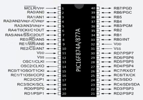
It has a total number of 40 pins out of which Port A has 6 pins, Port B, Port C, and Port D has 8 pins each, and port E has 3 pins. So from Port A to Port E, we have a total of 33 input and output pins. After that, we have two pins of VDD, two pins for VSS, one pin for MCLR which is the master clear pin of the microcontroller. Then we have one pin for OCS1 and one pin for OCS2 where the OCS1 is the oscillator input and OCS2 is the Oscillator output. These are the pins where the crystal oscillator is connected. The PIC microcontroller also consists of special pins like the RX and TX. The RX is serial input and TX is serial output. Together these two pins are used for asynchronous serial communication with the serial devices. After that, we have SCL and SDA pins where the SDA is serial data and SCL is a serial clock. These two pins from the two-wire I2C or integrated circuit of the PIC microcontroller. Then we have the four pins SD0, SDI, SCK, and the SS Pin. These four pins form the SPI or serial peripheral interface of the pic microcontroller. Now from AN0 to AN7, we have 10 bit ADC the analog to digital converter. Then we have RB0 which is the external interrupt pin for the pic microcontroller. CCP1 and CCP2 are the two PWM modules. PC0 to PC7 we have the parallel slave port with external read-write and CS control. The parallel slave port is 8 bit.
Arduino:
An atmega328 microcontroller is manufactured by ATMEL making you input voltage of around 7 volt or 12 volts to this port. The operating voltage of the microcontroller is 5 volt it has a CPU speed of 16 megahertz. There are analog inputs or output pins that are 6 in number.
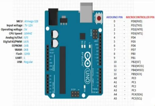
There are the 14 digital input/output pins out of which 6 can be used for pulse width modulation. The major feature of this pulse width modulation is it can be used to vary the intensity or the speed it has a EEPROM of 1 kb SRAM of 2 kb flash memory of 32kb which can be used to store the program or load the program. UART universal a synchronous receiving transmission of 1 USB type is regular it has a reset pin which when pressed the program is going to start from the first line. The pin numbers A4 and A5 which are analog pins has SDA and SCL input which can be used to receive a real-time clock configuration when used with ds1307. The digital pins 0 and 1 are used for serial communication 0 for receiving and 1 for transmission pin number 2 and 3 which is digital can also be used for interrupts purpose.
Atmega 328P description:
Atmega328 is low power CMOS 8 bit microcontroller based on enhanced AVR architecture. It has total number of 28 pins out of which 14 are digital output input pins from D0 to D13. It also has 6 ADC channels from A0 to A5 these form the analog to digital converter of the atmega328. It also has 6 pwm channels and two pins for XTAL1 and XTAL2.
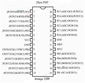
Two pins for ground. Pin number 7 and pin number 20 for VCC. Pin number 21 for analog reference. One pin for reset it low enabled input. So when this enabled go low the microcontroller reset and the program of the microcontroller also reset. One pin for RXD and one pin for TXD. The RXD and TXD form serial communication input of the microcontroller. The atmega328 also has some special pins like SCK which stands for serial clock, MISO stands for master input slave output, MOSI stands for master output slave input, SS stands for slave select. Together these four pins form serial peripheral interface of the atmega328. After that we have SCL and SDA which are the serial clock and serial data which form the I2C port of the atmega328. The operating voltage of this microcontroller ranges from 1.8V to 5.5V but typically we used 5V for this purposes. It can be combined with 16 Mhz Crystal oscillator along with 22pF capacitor to form the crystal oscillator circuit. We 32 KB of flash memory, 2KB of SRAM and about of 1 KB EEROM.
Arduino VS PIC:
Now we will compare the PIC microcontroller and Arduino UNO. First of all, Arduino is not actually a microcontroller it is a microcontroller board or development board. It has an AVR atmega328 microcontroller in it. PIC microcontroller is a family of microcontrollers made by microchip. They are mostly sold as chips and we need to put them on a circuit board by a sap socket and a few cables also external programmers like pick it 2 or pick 3 are needed to program the microcontroller using MPLAB X IDE. The software has less libraries as compared to Arduino UNO.
Arduino UNO is however is very cost-effective compared to PIC and it comes under open-source hardware cross platforms are also available as you can program it on Windows Linux and Mac while most of the pic microcontrollers are only programmable in Windows setup. The Arduino can be connected to the computer using a USB cable. Arduino has another microcontroller that acting as a programmer therefore it does not require an external device for programming. The programming environment is very easy to use even for beginners the library of examples is also present in IDE. So all you need is a USB cable Arduino software and Arduino board.
The PIC microcontroller is a program and developed using MPLAB X software. The MPLAB X software is free tool such as Arduino IDE but you have to pick the compiler yourself. We need more tools for the pic microcontroller. While in Arduino we only need an Arduino board, Arduino software, and USB cable. Sometimes we do not need a USB cable because the software is in it.
PIC microcontroller features:
| Operating Frequency | 48 MHz |
| Program memory | 32 Kb |
| Program memory (instruction) | 16 Kb |
| Data memory | 2 Kb |
| Data EEPROM | 256 |
| Interrupt sources | 20 |
| I /O ports | Port A, B, C, D, E |
| Timers | 4 |
| PWM modules | 1 |
| Serial communication | MSSP, Enhanced USART |
| USB | 1 |
| Streaming parallel port | Yes |
| 10 Bit analog to digital module | 13 input channels |
| Comparators | 2 |
| Packages | 40 pins PDIP
44 pin QFN 44 pin TQFP |
Arduino features:
| Operating Voltage | 5 V |
| Input Voltage | 7 – 12 V |
| Digital I/O pins | 14 |
| Analog input pins | 6 |
| DC current per I/O | 40 mA |
| DC current for 3.3V pin | 50 mA |
| Flash memory | 32 Kb |
| SRAM | 2 Kb |
| EEPROM | 1 KB |
| Clock Speed | 16 MHz |
| Timers | 4 |
| PWM modules | 6 |
| communication | Serial, UART, TTL, SPI |
Architecture:
Both a 8-bit RISC platforms so the base architecture is the same. PICs are older so they have more heritages in terms of knowledge but are also older technology and are not doing well keeping up with newer hardware verses cost. AVRs are newer and run faster with more features and have a support of open source tools (like the GCC compiler) and have cheap tools like the Dragon programmer and debugger.
We will not notice any difference when we are connecting relay, buttons or led but when we will using complex projects like hardware interfacing, data communication and large data processing, etc then we will feel the difference between the arduino and PIC. PICs have alot of legacy information out there but AVRs have cheap tools that make things easier (PIC does not have a good open source compiler AFAIK) which with code intensive projects can be helpful. This is why things like the Arduino platform can exist.
Which microcontroller is best?
The Arduino is best because it is user friendly as compared to the PIC microcontroller because if we want to load program in the Arduino we just click on the upload in the Arduino IDE while in case of PIC we will perform complex steps in order to upload the code in the controller also Arduino is helpful in complex projects.
Discover more from Electronic Clinic
Subscribe to get the latest posts sent to your email.


The pinguino is an Arduino like project using PIC, search GitHub for more.