ESP32 Web server based Home automation circuit diagram and programming
Last Updated on September 21, 2024 by Engr. Shahzada Fahad
Table of Contents
ESP32 Web server-based Home Automation:
ESP32 Web server based Home automation circuit diagram and programming– I have been using ESP32 WiFi + Bluetooth module for controlling electrical devices from anywhere in the world using the Blynk IoT platform which is no doubt one of the most popular IoT Platform for monitoring and controlling things over long distances. I have also used ESP32 with the IFTTT Google assistant for controlling AC and DC loads over long distances using WiFi as the communication medium.
When building a Home automation system or Office automation system I always prefer ESP32 over ESP8266; because the ESP32 comes with a built-in Bluetooth module that I can use for controlling things over a short distance. I have a very detailed tutorial on how to control AC and DC loads using the ESP32 built-in Bluetooth module and an Android cell phone application.
Recently, I built another Home Automation system using ESP32 and an IR remote controller for controlling 220Vac light bulbs. This IR remote controller-based Home automation system is for those guys who don’t want to rely on internet availability or don’t want to use a cell phone. I highly recommend you should watch this IR remote controller based Home automation system because today’s episode is entirely based on this project; as I will be using the same ESP32 development board, and the same lights. So, I will not explain the things which I have already explained in my previous article.
In today’s article, you will learn how to use ESP32 as the webserver and a cell phone or a laptop as the client for controlling home appliances or other electrical devices using WiFi as the communication medium. So, before I am going to explain the circuit diagram and programming; first, let’s watch this ESP32 Web server based Home Automation system in action.

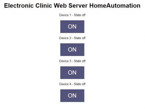
I simply started off by entering the IP address of the ESP32 module which I am using as the Webserver. I will explain in detail how to get this IP Address. You don’t have to design this web page, all the coding is done on ESP32 side, these buttons are automatically created but you have full control over all these buttons, you can change the design, you can increase or decrease the number of buttons. You can make all these changes in the ESP32 programming.
Anyways, you can also enter the IP address in your cell phone, and this way you can get access to the ESP32 Webserver. If you don’t want to use other IoT platforms then this is how you can design your own dashboard. You can also design your own gauges for displaying the sensors data. It depends on your interest and how much time you spend on coding.
I have been testing this project for the last 3 hours and I didn’t see any bugs, malfunction, and false triggering. Now, you have got the idea of what exactly you are going to learn after watching this video. Without any further delay, let’s get started!!!
Amazon Links:
ESP32 WiFi + Bluetooth Module(Recommended)
*Disclosure: These are affiliate links. As an Amazon Associate I earn from qualifying purchases.
ESP32 WiFi + Bluetooth Module:
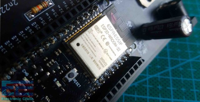
If you are just getting started with the ESP32 module then I highly recommend you should read my getting started article on the ESP32 module. I have explained everything in very detail like for example ESP32 comparison with ESP8266, ESP32 pinouts, technical specs, board installation, and libraries installations.
ESP32 Web server Home Automation Circuit Diagram:

J1 is the Dc female power jack and this is where we connect a 12v adaptor, battery or a solar panel. Two 470uf capacitors are connected at the input and output sides of the voltage regulator. The output of the voltage regulator is connected with the 5v pin of the ESP32 module and the ground of the power supply is connected with the ground of ESP32 module.
These are 12v SPDT type relays and can’t be directly controlled using the ESP32 Module, So, that’s why we need a driver to control these relays. You can use a relay driver IC or you can use 2n2222 NPN transistor and a 10k resistor. One pin of the relay coil is connected with the collector of the 2n2222 NPN transistor while the other pin of the relay coil is connected with the 12 volts. The emitter of the transistor is connected with the ground while the base is connected with the 10k ohm resistor.
Now to control these relays you simply need to connect these 10k resistors with the ESP32 I/O pins. In this project, I am using the GPIO pins 13, 12, 14, and 27. I will be using the same pins in the programming.
The neutral wire from the 110/220Vac supply is connected with the neutral of all the lights. While the Live wire from the AC supply is connected with the lights through these relays.
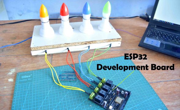
Here is my ESP32 development board, if you want to make the same development board then you can download the Gerber files. The lights connection with the relays remains exactly the same as I explained in my previous project “IR remote controller based Home automation”. Now, let’s take a look at the ESP32 Webserver based Home automation project programming.
ESP32 Web server Programming:
|
1 2 3 4 5 6 7 8 9 10 11 12 13 14 15 16 17 18 19 20 21 22 23 24 25 26 27 28 29 30 31 32 33 34 35 36 37 38 39 40 41 42 43 44 45 46 47 48 49 50 51 52 53 54 55 56 57 58 59 60 61 62 63 64 65 66 67 68 69 70 71 72 73 74 75 76 77 78 79 80 81 82 83 84 85 86 87 88 89 90 91 92 93 94 95 96 97 98 99 100 101 102 103 104 105 106 107 108 109 110 111 112 113 114 115 116 117 118 119 120 121 122 123 124 125 126 127 128 129 130 131 132 133 134 135 136 137 138 139 140 141 142 143 144 145 146 147 148 149 150 151 152 153 154 155 156 157 158 159 160 161 162 163 164 165 166 167 168 169 170 171 172 173 174 175 176 177 178 179 180 181 182 183 184 185 186 187 188 189 190 191 192 193 194 195 |
#include <WiFi.h> // Replace with your network credentials const char* ssid = "AndroidAP3DEC"; //WIFI Name const char* password = "electroniClinic"; //WIFI Password // Set web server port number to 80 WiFiServer server(80); // Variable to store the HTTP request String header; // Auxiliar variables to store the current output state String Device1State = "off"; String Device2State = "off"; String Device3State = "off"; String Device4State = "off"; // Assign output variables to Relay pins const int Device1 = 13; const int Device2 = 12; const int Device3 = 14; const int Device4 = 27; // Current time unsigned long currentTime = millis(); // Previous time unsigned long previousTime = 0; // Define timeout time in milliseconds (example: 2000ms = 2s) const long timeoutTime = 2000; void setup() { Serial.begin(115200); // Initialize the output variables as outputs pinMode(Device1, OUTPUT); pinMode(Device2, OUTPUT); pinMode(Device3, OUTPUT); pinMode(Device4, OUTPUT); // Set outputs to LOW digitalWrite(Device1, LOW); digitalWrite(Device2, LOW); digitalWrite(Device3, LOW); digitalWrite(Device4, LOW); // Connect to Wi-Fi network with SSID and password Serial.print("Connecting to "); Serial.println(ssid); WiFi.begin(ssid, password); while (WiFi.status() != WL_CONNECTED) { delay(500); Serial.print("."); } // Print local IP address and start web server Serial.println(""); Serial.println("WiFi connected."); Serial.println("IP address: "); Serial.println(WiFi.localIP()); server.begin(); } void loop(){ WiFiClient client = server.available(); // Listen for incoming clients if (client) { // If a new client connects, Serial.println("New Client."); // print a message out in the serial port String currentLine = ""; // make a String to hold incoming data from the client currentTime = millis(); previousTime = currentTime; while (client.connected() && currentTime - previousTime <= timeoutTime) { // loop while the client's connected currentTime = millis(); if (client.available()) { // if there's bytes to read from the client, char c = client.read(); // read a byte, then Serial.write(c); // print it out the serial monitor header += c; if (c == '\n') { // if the byte is a newline character // if the current line is blank, you got two newline characters in a row. // that's the end of the client HTTP request, so send a response: if (currentLine.length() == 0) { // HTTP headers always start with a response code (e.g. HTTP/1.1 200 OK) // and a content-type so the client knows what's coming, then a blank line: client.println("HTTP/1.1 200 OK"); client.println("Content-type:text/html"); client.println("Connection: close"); client.println(); // turns the Relays on and off if (header.indexOf("GET /1/on") >= 0) { Serial.println("Device 1 on"); Device1State = "on"; digitalWrite(Device1, HIGH); } else if (header.indexOf("GET /1/off") >= 0) { Serial.println("Device 1 off"); Device1State = "off"; digitalWrite(Device1, LOW); } else if (header.indexOf("GET /2/on") >= 0) { Serial.println("Device 2 on"); Device2State = "on"; digitalWrite(Device2, HIGH); } else if (header.indexOf("GET /2/off") >= 0) { Serial.println("Device 2 off"); Device2State = "off"; digitalWrite(Device2, LOW); } else if (header.indexOf("GET /3/on") >= 0) { Serial.println("Device 3 off"); Device3State = "on"; digitalWrite(Device3, HIGH); } else if (header.indexOf("GET /3/off") >= 0) { Serial.println("Device 3 off"); Device3State = "off"; digitalWrite(Device3, LOW); } else if (header.indexOf("GET /4/on") >= 0) { Serial.println("Device 4 off"); Device4State = "on"; digitalWrite(Device4, HIGH); } else if (header.indexOf("GET /4/off") >= 0) { Serial.println("Device 4 off"); Device4State = "off"; digitalWrite(Device4, LOW); } // Display the HTML web page client.println("<!DOCTYPE html><html>"); client.println("<head><meta name=\"viewport\" content=\"width=device-width, initial-scale=1\">"); client.println("<link rel=\"icon\" href=\"data:,\">"); // CSS to style the on/off buttons // Feel free to change the background-color and font-size attributes to fit your preferences client.println("<style>html { font-family: Helvetica; display: inline-block; margin: 0px auto; text-align: center;}"); client.println(".button { background-color: #52527a; border: none; color: white; padding: 16px 40px;"); client.println("text-decoration: none; font-size: 30px; margin: 2px; cursor: pointer;}"); client.println(".button2 {background-color: #d1d1e0;}</style></head>"); // Web Page Heading client.println("<body><h1>Electronic Clinic Web Server HomeAutomation</h1>"); // Display current state, and ON/OFF buttons for Relay 1 client.println("<p>Device 1 - State " + Device1State + "</p>"); // If the Device1State is off, it displays the ON button if (Device1State=="off") { client.println("<p><a href=\"/1/on\"><button class=\"button\">ON</button></a></p>"); } else { client.println("<p><a href=\"/1/off\"><button class=\"button button2\">OFF</button></a></p>"); } // Display current state, and ON/OFF buttons for Relay 2 client.println("<p>Device 2 - State " + Device2State + "</p>"); // If the Device2State is off, it displays the ON button if (Device2State=="off") { client.println("<p><a href=\"/2/on\"><button class=\"button\">ON</button></a></p>"); } else { client.println("<p><a href=\"/2/off\"><button class=\"button button2\">OFF</button></a></p>"); } // Display current state, and ON/OFF buttons for Relay 3 client.println("<p>Device 3 - State " + Device3State + "</p>"); // If the Device3State is off, it displays the ON button if (Device3State=="off") { client.println("<p><a href=\"/3/on\"><button class=\"button\">ON</button></a></p>"); } else { client.println("<p><a href=\"/3/off\"><button class=\"button button2\">OFF</button></a></p>"); } // Display current state, and ON/OFF buttons for Relay 4 client.println("<p>Device 4 - State " + Device4State + "</p>"); // If the Device4State is off, it displays the ON button if (Device4State=="off") { client.println("<p><a href=\"/4/on\"><button class=\"button\">ON</button></a></p>"); } else { client.println("<p><a href=\"/4/off\"><button class=\"button button2\">OFF</button></a></p>"); } client.println("</body></html>"); // The HTTP response ends with another blank line client.println(); // Break out of the while loop break; } else { // if you got a newline, then clear currentLine currentLine = ""; } } else if (c != '\r') { // if you got anything else but a carriage return character, currentLine += c; // add it to the end of the currentLine } } } // Clear the header variable header = ""; // Close the connection client.stop(); Serial.println("Client disconnected."); Serial.println(""); } } |
ESP32 Web server Code Explanation:
First, you will need to add the WiFi.h header file. Read my getting started tutorial on the ESP32 module which explains how to install the ESP32 board.
|
1 2 3 4 5 6 7 8 9 |
#include <WiFi.h> After that we will enter the Wifi name and password. // Replace with your network credentials const char* ssid = "AndroidAP3DEC"; //WIFI Name const char* password = "electroniclinic"; //WIFI Password |
Now, we will declare a variable server and write 80 in the parenthesis. Now a question will arise in your mind that why we are using 80 in it. So, the answer is simple 80 is the port number through which we will read the data. So the ESP32 will always be connected at port 80 because it is our server.
|
1 2 3 4 5 |
// Set web server port number to 80 WiFiServer server(80); // Variable to store the HTTP request |
Then we will declare the header variable of string type which will be used to start up the html.
|
1 |
String header; |
Then we will declare the variables which will be used in HTML programing, it will tells us the current status of the devices. At start, all the devices will be off; so, we have declared all the variables off.
|
1 2 3 4 5 6 7 8 9 |
// Auxiliar variables to store the current output state String Device1State = "off"; String Device2State = "off"; String Device3State = "off"; String Device4State = "off"; |
As we are going to connect the devices at the digital pins 12, 13, 14, and 27 of the ESP32 module. So, will declare the variables and pins with which we will connect the devices.
|
1 2 3 4 5 6 7 8 9 |
// Assign output variables to Relay pins const int Device1 = 13; const int Device2 = 12; const int Device3 = 14; const int Device4 = 27; |
Then we will define the time in which ESP32 will connect with the WiFi and if the ESP32 not connect in that time. It will gives us the timeout time.
|
1 2 3 4 5 6 7 8 9 10 11 12 13 14 15 16 17 18 19 |
// Current time unsigned long currentTime = millis(); // Previous time unsigned long previousTime = 0; // Define timeout time in milliseconds (example: 2000ms = 2s) const long timeoutTime = 2000; After that we will start the serial communication. void setup() { Serial.begin(115200); // Initialize the output variables as outputs |
Then we will declare all the relays with which all the devices are connected as output.
|
1 2 3 4 5 6 7 8 9 |
pinMode(Device1, OUTPUT); pinMode(Device2, OUTPUT); pinMode(Device3, OUTPUT); pinMode(Device4, OUTPUT); // Set outputs to LOW |
Then turn off all the relays so that no device will turn on when we will first run the project.
|
1 2 3 4 5 6 7 8 9 10 11 12 13 14 15 16 17 18 19 20 21 22 23 24 25 26 27 28 29 30 31 |
digitalWrite(Device1, LOW); digitalWrite(Device2, LOW); digitalWrite(Device3, LOW); digitalWrite(Device4, LOW); After that the ESP32 will start to connect the WiFi network. // Connect to Wi-Fi network with SSID and password Serial.print("Connecting to "); Serial.println(ssid); WiFi.begin(ssid, password); while (WiFi.status() != WL_CONNECTED) { delay(500); Serial.print("."); } // Print local IP address and start web server Serial.println(""); Serial.println("WiFi connected."); |
When the ESP32 module connects with the WiFi then the following lines of codes prints the IP address, we need that IP Address for opening the Web server page.
|
1 2 3 4 5 6 7 8 9 |
Serial.println("IP address: "); Serial.println(WiFi.localIP()); server.begin(); } void loop(){ |
This command will check whether there is any client who request for the data
|
1 2 3 4 5 6 7 8 9 10 11 12 13 14 15 16 17 18 19 20 21 22 23 24 25 26 27 28 29 30 31 32 33 34 35 36 37 38 39 40 41 42 43 44 45 |
WiFiClient client = server.available(); // Listen for incoming clients If this condition is true then the we will serial print that a new client and also mention the time. if (client) { // If a new client connects, Serial.println("New Client."); // print a message out in the serial port String currentLine = ""; // make a String to hold incoming data from the client currentTime = millis(); previousTime = currentTime; while (client.connected() && currentTime - previousTime <= timeoutTime) { // loop while the client's connected currentTime = millis(); if (client.available()) { // if there's bytes to read from the client, char c = client.read(); // read a byte, then Serial.write(c); // print it out the serial monitor header += c; if (c == '\n') { // if the byte is a newline character // if the current line is blank, you got two newline characters in a row. // that's the end of the client HTTP request, so send a response: if (currentLine.length() == 0) { // HTTP headers always start with a response code (e.g. HTTP/1.1 200 OK) // and a content-type so the client knows what's coming, then a blank line: client.println("HTTP/1.1 200 OK"); client.println("Content-type:text/html"); client.println("Connection: close"); client.println(); |
Now these commands will turn on and off the relays when the button is pressed on the html page. The “header.index” of will check that whether the button is on. If the button is pressed then the current status of the device will turn on and make the relay on to turn on the device. So, we will write similar code for all the relays. For example as in the html programing we have defined for the device1; if the button is pressed then it pass /1/on, so if the condition is true the device1 will turn on. This will be same for all the other buttons.
|
1 2 3 4 5 6 7 8 9 10 11 12 13 14 15 16 17 18 19 20 21 22 23 24 25 26 27 28 29 30 31 32 33 34 35 36 37 38 39 40 41 42 43 44 45 46 47 48 49 50 51 52 53 54 55 56 57 58 59 60 61 62 63 64 65 66 67 68 69 70 71 72 73 74 75 76 77 78 79 80 81 82 83 84 85 86 87 88 89 90 91 92 93 94 95 96 97 98 99 100 101 102 103 104 105 106 107 108 109 110 111 112 113 114 115 116 117 118 119 120 121 122 123 124 125 126 127 128 129 130 131 132 133 134 135 136 137 138 139 140 141 142 143 144 145 146 147 148 149 150 151 152 153 154 155 156 157 158 159 160 161 162 163 164 165 166 167 168 169 170 171 172 173 174 175 176 177 178 179 180 181 182 183 184 185 186 187 188 189 190 191 192 193 194 195 196 197 198 199 200 201 202 203 204 205 206 207 208 209 210 211 212 213 214 215 216 217 218 219 220 221 222 223 224 225 226 227 228 229 |
if (header.indexOf("GET /1/on") >= 0) { Serial.println("Device 1 on"); Device1State = "on"; digitalWrite(Device1, HIGH); } else if (header.indexOf("GET /1/off") >= 0) { Serial.println("Device 1 off"); Device1State = "off"; digitalWrite(Device1, LOW); } else if (header.indexOf("GET /2/on") >= 0) { Serial.println("Device 2 on"); Device2State = "on"; digitalWrite(Device2, HIGH); } else if (header.indexOf("GET /2/off") >= 0) { Serial.println("Device 2 off"); Device2State = "off"; digitalWrite(Device2, LOW); } else if (header.indexOf("GET /3/on") >= 0) { Serial.println("Device 3 off"); Device3State = "on"; digitalWrite(Device3, HIGH); } else if (header.indexOf("GET /3/off") >= 0) { Serial.println("Device 3 off"); Device3State = "off"; digitalWrite(Device3, LOW); } else if (header.indexOf("GET /4/on") >= 0) { Serial.println("Device 4 off"); Device4State = "on"; digitalWrite(Device4, HIGH); } else if (header.indexOf("GET /4/off") >= 0) { Serial.println("Device 4 off"); Device4State = "off"; digitalWrite(Device4, LOW); } // Display the HTML web page Now, this command show that we are sending html page client.println("<!DOCTYPE html><html>"); Then we will set the page size client.println("<head><meta name=\"viewport\" content=\"width=device-width, initial-scale=1\">"); client.println("<link rel=\"icon\" href=\"data:,\">"); // CSS to style the on/off buttons After that we will the write the code in which we define the color of the text, size, type and set it in the centre. // Feel free to change the background-color and font-size attributes to fit your preferences client.println("<style>html { font-family: Helvetica; display: inline-block; margin: 0px auto; text-align: center;}"); then we will define the button color, size and its background color. client.println(".button { background-color: #52527a; border: none; color: white; padding: 16px 40px;"); client.println("text-decoration: none; font-size: 30px; margin: 2px; cursor: pointer;}"); then we will define the properties for the second button 2 which will be appear when we will press the button all the properties will be similar to that of 1 only difference will be in color. client.println(".button2 {background-color: #d1d1e0;}</style></head>"); then we will give the heading to html page which will appear at the top when we will open the html. // Web Page Heading client.println("<body><h1>Electronic Clinic Web Server HomeAutomation</h1>"); then we declare the current state of the device. So when we will press the button it will pass the command and will change the state. // Display current state, and ON/OFF buttons for Relay 1 client.println("<p>Device 1 - State " + Device1State + "</p>"); // If the Device1State is off, it displays the ON button if (Device1State=="off") { client.println("<p><a href=\"/1/on\"><button class=\"button\">ON</button></a></p>"); } else { client.println("<p><a href=\"/1/off\"><button class=\"button button2\">OFF</button></a></p>"); } // Display current state, and ON/OFF buttons for Relay 2 client.println("<p>Device 2 - State " + Device2State + "</p>"); // If the Device2State is off, it displays the ON button if (Device2State=="off") { client.println("<p><a href=\"/2/on\"><button class=\"button\">ON</button></a></p>"); } else { client.println("<p><a href=\"/2/off\"><button class=\"button button2\">OFF</button></a></p>"); } // Display current state, and ON/OFF buttons for Relay 3 client.println("<p>Device 3 - State " + Device3State + "</p>"); // If the Device3State is off, it displays the ON button if (Device3State=="off") { client.println("<p><a href=\"/3/on\"><button class=\"button\">ON</button></a></p>"); } else { client.println("<p><a href=\"/3/off\"><button class=\"button button2\">OFF</button></a></p>"); } // Display current state, and ON/OFF buttons for Relay 4 client.println("<p>Device 4 - State " + Device4State + "</p>"); // If the Device4State is off, it displays the ON button if (Device4State=="off") { client.println("<p><a href=\"/4/on\"><button class=\"button\">ON</button></a></p>"); } else { client.println("<p><a href=\"/4/off\"><button class=\"button button2\">OFF</button></a></p>"); } client.println("</body></html>"); // The HTTP response ends with another blank line client.println(); // Break out of the while loop break; } else { // if you got a newline, then clear currentLine currentLine = ""; } } else if (c != '\r') { // if you got anything else but a carriage return character, currentLine += c; // add it to the end of the currentLine } } } // Clear the header variable header = ""; // Close the connection client.stop(); Serial.println("Client disconnected."); Serial.println(""); } } |
Upload the code into the ESP32 module. To control the home appliances or other electrical loads using a webpage; first, we will need the IP address of the ESP32 module which we are using as the Webserver. Now, to find the IP address; first, we will need to connect the ESP32 module with the Laptop. Next, open the serial monitor and make sure the ESP32 module is connected with the WiFi.

Copy the IP address for this simply press Ctrl + C on the keyboard. After this disconnect the USB cable, power up the ESP32 module, I am using my homemade 4S lithium Ion Battery pack, if you want you can use a 12V adaptor. Next, connect the 110/220Vac wires to power up the lights.
Finally, open the internet browser, paste the IP Address and press the enter key on your keyboard and start controlling your Home appliances, in my case, I am controlling 4 lights. While the 110/220Vac wires are connected never touch the relay contacts, as it can be really dangerous. So, that’s all for now.
Watch Video Tutorial:

Discover more from Electronic Clinic
Subscribe to get the latest posts sent to your email.


