I2C Serial Communication Bus in Raspberry pi
Table of Contents
I2C bus in Raspberry pi:
I2C bus represents another interface of the Raspberry Pi. Also for this system there are some external building blocks that are used with the Raspberry Pi can bus. I2C stands for Inter-Integrated Circuit and unlike the SPI bus, only uses two wires. The required connections on the Raspberry Pi are pin 3 SDA and the pin 5 SCL. One advantage over the SPI bus is that when using it multiple participants on the bus no separate chip select signal the participants dials. With the I2C bus, each participant has an address that is addressed individually. The modules often also offer the option of using jumpers or Jumpers to change the address. So several components of the same type different addresses can be assigned in order to have them on the Raspberry To use pi.
In this article we refer primarily to the first channel (I2C1) of the I2C protocol. This can be reached via pins 3 and 5. Channel 0 (I2C0) can also be activated, but is mainly reserved for EEPROMs. I2C0 is through the pins 27 and 28 executed. The I2C bus usually uses open collector inputs. It means that the corresponding I2C components do not have their own voltage level on their I2C Pins to lead. The SDA and SCL pins of the Raspberry Pi are connected by internal pull-up Resistors pulled to a 3.3v level. The bus participants switch to the Communication this level only to ground. So there are also 5 V I2C components no 5V on the bus pins.
Nevertheless, if you have the opportunity to use your components, sensors or ICs with to supply 3.3 V, you should use this option. Because a circuit that consistently carries a maximum of 3.3 V, minimizing the risk of damaging the Raspberry Pi.
Amazon Purchase Links:
Wireless Keyboard and Mouse for raspberry pi:
Night vision Camera for Raspberry Pi:
Oled HDMI touch display for raspberry pi:
Other Tools and Components:
Super Starter kit for Beginners
PCB small portable drill machines
*Please Note: These are affiliate links. I may make a commission if you buy the components through these links. I would appreciate your support in this way!
The I2C bus is deactivated by default and can be activated by setting in raspi config Menu. Call the settings menu through the command sudo raspi-config and navigate to point 8 Advanced Options. In the following from the menu screen select the item A7 I2C and answer the two upcoming queries with Yes. The first confirmation activates the I2C bus, and the second ensures that this remains available immediately after every system start.
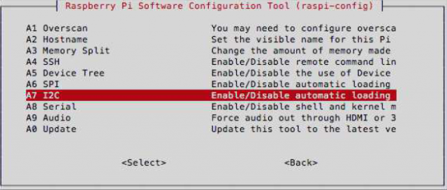
Behind the scenes, raspi-config creates the entry dtparam = i2c_arm = on in the file /boot/config.txt. This activates the I2C interface in the new device tree. Unfortunately raspi-config does not automatically load the i2c-dev module that is used to access the interface must be available. Hence it is necessary that you do it manually to the file / ect / modules /.
Open the file /etc/modules with:
|
1 2 3 4 5 |
nano / etc/modules Add this line to the end of the file: # / Etc / modules ... i2c - dev |
Then save and close the file. The I2C module should now be loaded after a restart. Remember that this means that I2C bus 1 can be used is. You can find this at pins 3 and 5. Bus 0 (pins 27 and 28) is in the new one Raspberry Pi models reserved for the EEPROMs of the so-called HATs. these are new, standardized expansion boards for the Raspberry Pi. If you still want to activate the bus, add the line dtparam = i2c0 in the file /boot/config.text.
The port expander MCP23017:
The MCP23017 is a popular component with the I2C protocol. It is about a port expansion module. With the MCP23017 you have the option of add up to 16 additional inputs and outputs to the Raspberry Pi. You sacrifice only the SCL and SDA connection of the Raspberry Pi to connect the module with the Connect bus. Now let’s look at the pin assignment again first (see Figure 2).
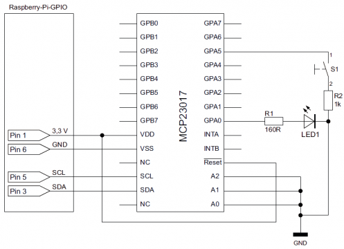
GPA 0–7: Bank A of the available ports
GPB 0–7: Bank B of the available ports
VDD: supply voltage. The MCP23017 requires at normal room temperature a supply voltage of 1.8 V to 5.5 V. Connect the 3.3 V of the Raspberry Pi.
VSS: ground
NC: Not connected. These pins are not used and have no function.
SCL: Serial Clock Line. Part of the I2C bus.
SDA: Serial Data Line. Also part of the bus system.
Reset: Low active reset pin. This pin must be high, i.e. 3.3 V, so the block works.
A0-A2: addressing bits. These pins offer the possibility to change the address on the Change bus. Depending on the combination of high and low levels on these pins you can change the address. With 3 bits you have a total of 8 addressing options. In theory, you can do eight like this without any additional effort Operate the MCP23017 port expander on the I2C bus.
INTA, INTB: These two connections are interrupt pins. These pins can do so can be configured to provide a signal when the status of a port changes on the component changes. This can be useful if the software does not receive any input permanently monitored. A status change can also be recorded if the Software is doing something different. See for configuring these ports in the data sheet of the component.
As soon as you have activated the I2C bus and connected the component as shown on the circuit diagram you can continue installing the required software. Now install the i2c-tools package. This package enables with simple commands I2C communication directly from bash. The installation of i2c-tools is not mandatory. However, we highly recommend the little program because you test, read out and also with very short commands every I2C bus participant can describe.
sudo apt – get install i2c – tools
i2cdetect checks whether the component is recognized on the bus (see Figure 3):
i2cdetect -y 1
A brief explanation of the syntax:
i2cdetect: Command from i2c-tools to find I2C peripherals
-y: execute command without asking (are you sure?)
1: number of the bus. Bus 1 uses pins 3 and 5. Bus 0 is usually for that EEPROM reserved on the HAT boards, but can be accessed via pins 27 and 28 will.
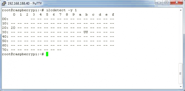
You can see from the output that the block is at address 0x20. Change The high / low combination at pins A0-A2. So you can watch how the address changes. If all pins are on GND, 0x20 is the standard address of the MCP23017. If you do not get a value, check the correct one Wiring the module. In the circuit diagram we have connected an LED to GPA0 and a button to GPA5 (see Figure 2). Let’s look at the LED first. To GPA0 now as an output To define and go high, you need to go back to some important tables from the data sheet (see Figure 4).
The white lines relate to bank A, ie GPA0–7, the colored lines to Bank B, GPB0-7. Our LED is connected to GPA0, so only the white ones are Lines of interest. In the initial state, all 16 ports of the MCP23017 are as inputs Are defined. To control the LED, however, GPA0 must be declared as an output will. This can be done in the IODIRA register. You can read the abbreviation as input / output direction A. The second column gives you the address of the IODIRA register, namely 0x00 (Address (hex)). GPA0 can be found in the penultimate column as IO0 under bit 0.
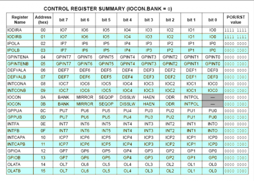
Now you know the required values and can also access them from the shell for the component send. To do this, use another command from the i2c tools:
i2cset -y 1 0 x20 0x00 0xFE
Explanation of the syntax:
- i2cset: Command from the i2c tools for writing on the I2C bus
- -y: execute command without prompt (are you sure?)
- 1: number of the bus
- 0x20: Address of the block to be written
- 0x00: This is the address of the IODIRA register.
- 0xFE: This value sets bit 0 of the IODRA register to 0 and thus as an output.
If you are wondering where the hex value 0xFE comes from, throw again take a look at the table of available registers. In the last column of the table you can see that all bits of the IODIRA register are 1 in the initial state. A 1 in one bit of this register defines the corresponding port as an input. Around to make it an output, change the corresponding bit to a 0. As Expressed as a binary number, it would look like this in our case:
11111110
GPA7–1 remain as an input. GPA0, i.e. the last bit, changes its Status of an output. Convert the binary number into a hex value, like this you will get 0xFE.
As soon as you confirm the command and press enter, it will be executed without any further message. GPA0 is now an output, but not yet active. Switch with the next command The LED on. To do this, look again in the table on the data sheet. The In this case, the necessary register is OLATA (Output Latch A). The address of the register is 0x14. Here, too, the searched bit for GPA0 is bit 0. This time, however, there is a 1 is required. Now use i2cset to write into the OLATA register in bit 0
a 1:
i2cset -y 1 0 x20 0x14 0x01
The syntax remains the same as in the previous command. Only the register address and the bit values have changed. Once you’ve confirmed the command, it should the LEDs light up. GPA0 now has a high level.
With this principle you can now switch all 16 outputs as required. The register overview from the data sheet gives you all the information you need. If you bank B, i.e. GPB 0–7, use the registers IODIRB and OLATB. Let us now dedicate ourselves to the button connected to the GPA5: To read the button status GPA5 must be declared as an input. This should already be the case. Otherwise use the i2cset command again to separate GPA5 into an input to change:
i2cset -y 1 0 x20 0x00 0x20
After sending this command, GPA5 is an input, all other ports are outputs. The explanation for this is again in the binary code of 0x20:
00100000
The i2c-tools still have the i2cget command. Use this to get data to receive on the bus. To read the status of GPA5, drag the value directly from the output register GPIOA with the address 0x12:
i2cget -y 1 0 x20 0x12
The command should now return a hex value. If you use the command several times in a row try it out, the value read does not seem to remain stable. The has the reason that the circuit initially sketched in the circuit diagram does not have a pull-up Has resistance that always pulls the level to a defined value. We have The pull-up resistor is deliberately omitted here so that we can give you the function the internal pull-up.
The pull-up registers are hidden behind the register names GPPUA and GPPUB. So let’s connect a pull-up resistor to GPA5:
i2cset -y 1 0 x20 0x0C 0x20
Submit the command and now try again to GPA5 with the i2cget command read out. If you have followed every step up to this point exactly, the LED should still be lit. The output from i2cget in this case is 0x21. Calculate this value back to a binary number, you can see directly which ports are active:
00100001
You can see that bit 0 (GPA0) and bit 5 (GPA5) are active. Now press the button, and read out the data again. The output changes to 0x01. Corresponding following binary code:
00000001
GPA5 was pulled to ground by pressing the button and thus returns a 0 back. Reading also works in bank B according to the same scheme. Read To do this, simply go to the GPIOB output register and write the pull-up Values in GPPUB.
I2C in Python
To conclude this section, we will show you an example of the I2C application in python. To use I2C in Python, you need the Python Library smbus. You reinstall this library with the package manager:
sudo apt – get install python – smbus
Since we want to use Python 3 again in this example, one follows Modification of the smbus library. If you use smbus under Python 2.x, skip this Now the following points. Install a necessary package:
sudo apt – get install libi2c – dev
In the next step you download the source files of the i2c tools and unzip them this and change to the newly created directory:
wget http: // ftp .de. debian. org / debian / pool / main / i / i2c – tools / i2c –
tools_3 .1.0. orig. tar. bz2
tar xf i2c – tools_3 .1.0. orig. tar. bz2
cd i2c – tools -3.1.0 / py – smbus
To be on the safe side, you should now rename the file to be modified to back up:
mv smbusmodule .c smbusmodule .c. backup
The next command downloads and replaces the modified library C file now the original file:
wget https: // gist. githubusercontent .com / sebastianludwig / \
c648a9e06c0dc2264fbd / raw / \
2 b74f9e72bbdffe298ce02214be8ea1c20aa290f / smbusmodule .c
The last two commands create and install the library in the Python 3 Surroundings:
sudo python3 setup .py build
sudo python3 setup .py install
After the installation, the library can be used directly:
|
1 2 3 4 5 6 7 8 9 10 11 12 13 14 15 16 17 18 19 |
#! / usr / bin / python3 import smbus, time bus = smbus. SMBus (1) address = 0x20 # I2C address of the MCP23017 def get (register): read = bus. read_byte_data (address, register) return read def set (register, data): write = bus. write_byte_data (address, register, data) return set (0x00, 0x20) while True: state = get (0x12) print (state) if state == 0x00: set (0x14, 0x01) print ("Button recognized, LED on!") time. sleep (1) set (0x14, 0x00) |
The Python program defines the functions for reading and writing. In the while loop is checked every second whether the button on GPA5 has been pressed. Is if this is the case, the LED lights up for one cycle. The Python program is used thus as an example to learn how to use smbus.
