KY-017 Mercury tilt sensor Switch with Arduino circuit Diagram & Code
Last Updated on August 17, 2024 by Engr. Shahzada Fahad
Table of Contents
KY-017 Mercury tilt sensor:
In this article we take a look at two sensors the KY-17 and the KY-27. The reason we look at two sensors is these shields have the same built-in sensor and that’s called a mercury tilt switch. Both the sensors work similarly the only difference is the KY027 has built-in led.
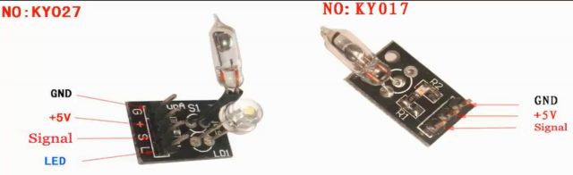
The mercury tilt sensor is a tilt sensor which opens and closes an electrical circuit when it is inclined beyond a certain angle. It can be used in tilt prevention device, an alarm circuit, and in many DIY projects. There are different types of tilt switch sensor modules for sensing the tilt and module can have a ball switch or mercury switch.
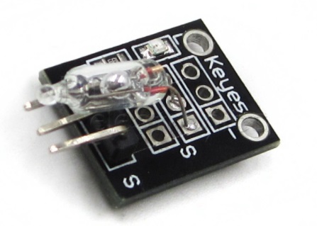
Mercury based tilt sensor requires a 5 volt of DC input. It is a three terminal device consists of input ground and out. It has a glass tube consists of two electrodes and liquid mercury ball. The liquid mercury ball closes and opens the circuit when inclined in a particular direction.
Amazon Links:
Arduino Nano USB-C Type (Recommended)
*Disclosure: These are affiliate links. As an Amazon Associate I earn from qualifying purchases.
Working of the Mercury Tilt Sensor:
Case 1: Not Tilted
in this, the first case is not tilted initially. When it is in not tilted position as shown in the image it gives low output because of the liquid mercury complete the circuit by connecting the two electrodes. When the output is low on board LED remain on.

Case 2: Tilted
In the case2, the sensor is tilted, mercury is inclined in a particular direction or angle. The liquid mercury breaks the contact between the metal electrodes and the circuit gets open. Hence we get high output in this condition and the onboard LED turns off.

Inside this glass is a liquid and that liquid is mercury and mercury is extreme toxic so watch out be careful at all times, if the glass is leaking throw out the sensor away and do not touch it with your skin. This is how it works there are three wires inside the glass envelope a“+” , “-” and signal and the mercurydot is always connected with the with the signal wire and when it tilts it connects the signal with the plus and then you have a signal in the other side it connects the mercury with the “–“.

These kinds of sensors are a little bit outdated you are not good enough to use in mobile devices and because of the toxic it’s not used in the food process; in the past those sensors have been used a lot in the industry.
Interfacing of the Mercury Tilt Sensor with Arduino:
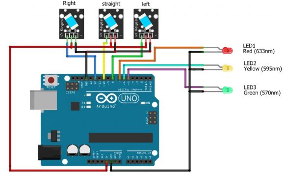
Now, let us consider, we have three mercury sensors and we connect three leds with these sensors. Such that we connect signal pin of right mercury sensor with the pin number 12, connect the signal pin of the straight mercury sensor with the digital pin number 10 and connect the left mercury sensor with the digital pin number 8. Connect the middle pin of all Mercury Tilt Sensors with the 5 V of the Arduino and connect the ground pin of all Mercury sensors with the ground of the Arduino. Now we will connect the 3 LEDs such that connect the anode of the red led with the digital pin number 7, connect the anode of the yellow led with the digital pin number 6, and connect the anode of the green led with pin number 5. Connect the cathode of all the LEDs with the ground pin. Now our circuit is completed and we will write the code for this circuit. I am using 5v LEDs, if you are using standard 2.5v leds then don’t forget to add the current limiting resistors of 330 ohms.
Mercury Tilt Sensor Arduino Code:
|
1 2 3 4 5 6 7 8 9 10 11 12 13 14 15 16 17 18 19 20 21 22 23 24 25 26 27 28 29 30 31 32 33 34 35 36 37 38 39 40 41 42 43 44 45 46 47 48 49 50 51 52 53 54 55 56 57 58 59 60 61 62 63 64 65 66 67 68 69 70 71 72 73 74 75 |
int LedPinA = 7; int LedPinB = 6; int LedPinC = 5; int ButtonPinA = 12; int ButtonPinB = 10; int ButtonPinC = 8; int buttonStateA = 0; int buttonStateB = 0; int buttonStateC = 0; int brightnessA = 0; int brightnessB = 0; int brightnessC = 0; void setup () { pinMode (LedPinA, OUTPUT); pinMode (LedPinB, OUTPUT); pinMode (LedPinC, OUTPUT); pinMode (ButtonPinA, INPUT); pinMode (ButtonPinB, INPUT); pinMode (ButtonPinC, INPUT); } void loop () { tiltLeft(); tiltRight(); tiltStraight; delay(25); } void tiltLeft(){ buttonStateA = digitalRead (ButtonPinA); if (buttonStateA == HIGH && brightnessA != HIGH) { brightnessA= HIGH; digitalWrite(LedPinA,brightnessA); } else{ brightnessA = LOW ; digitalWrite(LedPinA,brightnessA); } } void tiltRight(){ buttonStateC = digitalRead (ButtonPinC); if (buttonStateC == HIGH && brightnessC != HIGH) { brightnessC = HIGH; digitalWrite(LedPinC,brightnessC); } else{ brightnessB = LOW; digitalWrite(LedPinC,brightnessC); } } void tiltStraight(){ buttonStateB = digitalRead (ButtonPinB); if (buttonStateB == HIGH && brightnessB != HIGH) { brightnessB = HIGH; digitalWrite(LedPinB,brightnessB); } else{brightnessC = LOW; digitalWrite(LedPinB,brightnessB); } } |
Code Explanation:
First of all we will declare the leds which are connected with the Arduino. In our project we are using three leds which are red, yellow, and green. As we have connected these leds at pin number 7, 6, and 5 respectively, so we will define it in the code.
Int LedPinA = 7;
Int LedPinB = 6;
Int LedPinC = 5;
In the next step we define the pins used for the mercury sensors which are 12, 10, and 8.
Int ButtonPinA = 12;
Int ButtonPinB = 10;
Int ButtonPinC = 8;
Then we will set the variable in which we will note the current state of the mercury sensor to find that whether the current state of the LED is high or low.
Int buttonStateA = 0;
Int buttonStateB = 0;
Int buttonStateC = 0;
Brightness variable will be used to set the brightness of the led in which LOW means the led is off and HIGH means the led is turned on.
Int brightnessA = 0;
Int brightnessB = 0;
Int brightnessC = 0;
Now, in the setup function we will declare the led as output means that it will be turned on when the mercury sensor will detect any movement.
void setup ()
{
pinMode (LedPinA, OUTPUT);
pinMode (LedPinB, OUTPUT);
pinMode (LedPinC, OUTPUT);
The mercury sensor signal pins will be declared as input in order to read the current state of the mercury sensor.
pinMode (ButtonPinA, INPUT);
pinMode (ButtonPinB, INPUT);
pinMode (ButtonPinC, INPUT);
}
Now in the loop function we will declare three functions which will show that whether the left sensor is turned on, right sensor, or straight sensor.
void loop ()
{
tiltLeft();
tiltRight();
tiltStraight;
delay(25);
}
Now if the left sensor is high means it detected the motion then:
Void tiltLeft(){
Read the current state of the sensor
buttonStateA = digitalRead (ButtonPinA);
After reading the current state of the sensor, if the sensor is high and brightnessA != HIGH means the led is not turned on then turn on the led.
if (buttonStateA == HIGH &&brightnessA != HIGH)
{
brightnessA= HIGH;
digitalWrite(LedPinA,brightnessA);
}
Otherwise the led will be turned off
else{brightnessA = LOW;}
}
Similar process will be used for the right sensor, if it is high then turn on the led and if the statement is false turn off the led.
Void tiltRight(){
buttonStateC = digitalRead (ButtonPinC);
if (buttonStateC == HIGH &&brightnessC != HIGH)
{
brightnessC = HIGH;
digitalWrite(LedPinC,brightnessC);
}
else{
brightnessB = LOW;
digitalWrite(LedPinC,brightnessC);
}
}
Void tiltStraight(){
buttonStateB = digitalRead (ButtonPinB);
if (buttonStateB == HIGH &&brightnessB != HIGH)
{
brightnessB = HIGH;
digitalWrite(LedPinB,brightnessB);
}
else{brightnessC = LOW;
digitalWrite(LedPinB,brightnessB);
}
}
The working of the circuit will be such that when we will move the sensor, according to the movement of the sensor the led will turn on; for example if we tilt the right sensor the green led will turn on. If we tilt the straight sensor the yellow led will turn and similarly if we tilt the left sensor the red led will turn on.
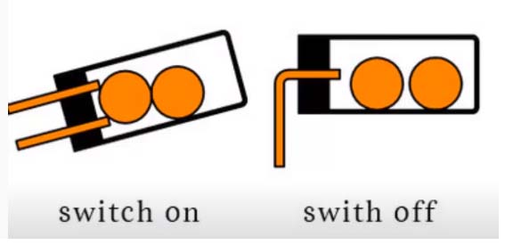
KY-020 tilt Ball Switch Sensor:
This sensor closes the circuit when it is tilted to the side as long as it is moved with enough force and degree of inclination to activate the ball switch inside.
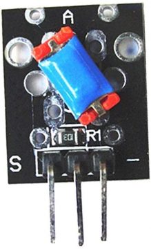
It consist of balls, when the balls will be close to one another the switch will be turned on and when the ball will move away from each other the switch will be closed. The balls moves according to the tilt angle of the sensor.
Tilt Ball Switch Sensor Specification:
The KY-020 Tilt Ball Switch Sensor consists of a 10KΩ resistor and a metallic ball switch with bi-directional conduction that will open/close the circuit depending on its tilt degree. It does not measure the tilt angle.
Operating voltage: 3.3 to 5
Output Type: digital
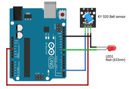
Interfacing the Tilt ball Switch sensor with the Arduino:
- Connect the signal pin of the Tilt ball sensor with the Arduino digital pin number 2
- Connect the VCC pin of the sensor with the 5V
- Connect the ground pin of the sensor with the ground of the Arduino
- Connect the anode of the led with the digital pin number 9
- Connect the cathode of the led with the ground
KY-020 Tilt Ball Switch Arduino Code:
|
1 2 3 4 5 6 7 8 9 10 11 12 13 14 15 16 17 18 19 20 21 |
int tiltPin = 2; // pin number for tilt switch signal int ledPin = 9; // pin number of LED int tiltState = 0; // variable for reading the tilt switch status void setup() { pinMode(ledPin, OUTPUT); // set the LED pin as output pinMode(tiltPin, INPUT); // set the tilt switch pin as input } void loop(){ // get the tilt switch state tiltState = digitalRead(tiltPin); // check if tilt switch is tilted. if (tiltState == HIGH) { digitalWrite(ledPin, HIGH); } else { digitalWrite(ledPin, LOW); } } |
Now after uploading the code to the Arduino, when we will tilt the sensor the led will turn on.
Discover more from Electronic Clinic
Subscribe to get the latest posts sent to your email.


