L9110 motor Driver with Arduino, Code & Circuit Diagram
Table of Contents
L9110 Motor Driver with Arduino:
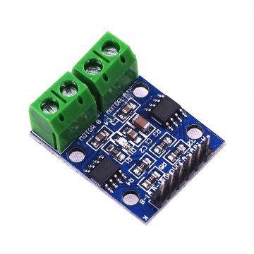
L9110 Motor driver with Arduino, Code, & Circuit Diagram- The L9110S 2-Channel motor driver module is a compact board that can be used to drive small robots. This module has two independent motor driver chips which can each drive up 800mA of continuous current. The board can be operated from 2.5V to 12V enabling this module to be used with both 3.3V and 5V microcontrollers.
In this tutorial I will show you how to use the L9110 motor driver board and write simple Arduino code to control various types of motors in your own personal projects. The L9110 Motor Driver is a compact and inexpensive h-bridge motor control board that easily interfaces with microcontroller boards such as the Arduino, Raspberry Pi, ESP32, STM32, Nodemcu ESP8266, etc. The L9110 Motor Driver can be used to control two small DC motors simultaneously or can be used to control a small stepper motor. The motor driver can operates between two and a half up to 12 volts DC and is capable of sourcing 800 milliamps per phase sustained or one-and-a-half amps momentarily. The L9110 Motor driver is very similar to the L298N but with a little less functionality but as you can see it issignificantly more compact and also has a much lower cost.
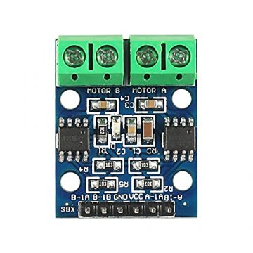
The L9110 Motor Driver Control Board measures about 30 millimetres long and about 23 millimeters wide is about 15 millimeter stall with the terminals and pin headers installed but have a much lower profile with them removed. The board has four, three millimeter mounting holes, each board has two L9110 chips, each chip can control the speed and direction of one DC motor, each motor has its own terminal block, motor A is on the right motor B is onthe left.
Specifications
- On-board 2 L9110 motor control chip
- Module can be driven by two dc motors at the same time or one phase 4 line 2 type stepping motor
- Input voltage: 2.5-12V DC
- Each channel has a continuous output current 800 ma
- PCB Size: 29.2mm x 23mm
Pins of the L9110:
Now let’s talk about the pin headers, the third pin from the left is the ground pin and should be connected to the negative terminal of your power supply. To the right is the VCC pin which should be connected to the positive terminal of your power supply.
The onboard LED indicates when the board has power, I do not recommend connecting ground and VCC to your Arduino as this can overload the power supply depending on the power required to drive the motors. The two pins on the right are for controlling motor A and the two pins on the left are for controlling motor B. The pins are either labeled 1a or 1b we will discuss that more in a minute these are the pins that need to be connected to the Arduino. Now if you are only concerned about motor direction you can use regular digital high-low output pins. If you want to control speed and direction you will need to use pulse width modulation PWM pins a potential of atleast 2.5 volts is required for the control board to recognize a high signal. So keep that in mind when selecting your microcontrollers both Arduino and Raspberry Pi will work fine for with this board.
Amazon link:
Arduino Nano USB-C Type (Recommended)
*Please Note: These are affiliate links. I may make a commission if you buy the components through these links. I would appreciate your support in this way!
L9110 Connection with Arduino:
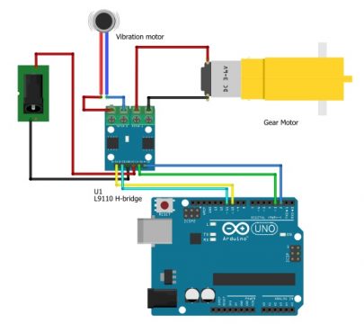
let’s connect a motor to channel a and demonstrate the basics of direction control using the digital write command. For this example, I will use a gear motor so that we can easily see the motor direction. Let’s wire this up and then write some Arduino code to demonstrate. If you know the polarity of your motor, connect the positive wire of the motor to the motor “A” connector on the left and the negative wire to the connector on the right. If you do not know the polarity don’t worry about it. It will be very easy to fix, if your motor spins opposite of what you wanted for this demonstration then the change the wire connection.
I will be using 10 volts from my power supply, first I will connect the positive to VCC and the negative to ground. If I were using say a 12 volt battery for the motor control board and a 9-volt battery for the Arduino I would want to make sure the ground pin on the motor control board and the ground pin on the Arduino are both connected to a common reference for Direction control only I can select any two digital output pins on the Arduino I will connect Arduino pin 3 to a1a on the control board and Arduino pin 2 to a1 B.
Counter clockwise direction of motor:
If we give a high command to pin a1a and a low command to pin a1b the motor will spin counterclockwise.
Clockwise direction of motor:
When looking at the end of the shaft if we give a low command to pin a1a and a high command to pin a1b the motor will spin clockwise.
If we give a high command to both channels or low command to both channels the motor will not spin.
L9110 Motor Driver Arduino Code:
|
1 2 3 4 5 6 7 8 9 10 11 12 13 14 15 16 17 18 19 20 |
constint A1A=3; constint A1B=2; void setup() { // put your setup code here, to run once: pinMode(A1A, OUTPUT); pinMode(A1B, OUTPUT); } void loop() { // put your main code here, to run repeatedly: digitalWrite(A1A,LOW); digitalWrite(A1B,HIGH); delay(2000); digitalWrite(A1A,HIGH); digitalWrite(A1B,LOW); delay(2000); } |
L9110 Motor Driver Arduino Code Explanation:
Let’s write some basic Arduino code to demonstrate. First we needed to find what pins on the Arduino correspond with the pins on the motor control board. We will create a constant integer for A1A as pin 3 and A1B as pin 2:
constint A1A=3;
constint A1B=2;
In our setup function we will set the pin modes for both pins as outputs.
pinMode(A1A, OUTPUT);
pinMode(A1B, OUTPUT);
Clockwise direction
In the loop we will set pin A1A low and pin A1B high, this will cause the motor to spin in a clockwise direction. We will hold this direction for 2 seconds using the delay command.
digitalWrite(A1A,LOW);
digitalWrite(A1B,HIGH);
delay(2000);
Counter clockwise direction:
Now we will switch pin A1A to high and A1B to low, this will cause the motor to spin in the opposite direction and we will hold it in that state for another 2 seconds.
digitalWrite(A1A,HIGH);
digitalWrite(A1B,LOW);
delay(2000);
Make sure to select the correct board and serial port to upload the sketch. I have connected the end on the Arduino to the 10 volts on my breadboard also ground to ground. let’stest it out by turning on the power supply the motor will change its direction after 2 seconds. The test was successful.
Adding second vibration motor:
Now let’s add a second motor to channel B and demonstrate Motor driver. I have connected the vibrating motor to the control board, I have also connected B1B on the control board to Arduino pin11and B1A pin to Arduino pin10.
I selected pins 10 and11 because they are both capable of pulse width modulation
L9110 and Vibration Motor, Arduino code:
|
1 2 3 4 5 6 7 8 9 10 11 12 13 14 15 16 17 18 19 20 21 22 23 24 25 26 |
const int A1A=3; const int A1B=2; const int B1A=10; const int B1B=11; int speed=51; void setup() { // put your setup code here, to run once: pinMode(A1A, OUTPUT); pinMode(A1B, OUTPUT); pinMode(B1A, OUTPUT); pinMode(B1B, OUTPUT); } void loop() { // put your main code here, to run repeatedly: analogWrite(B1B,0); analogWrite(B1A,speed); digitalWrite(A1A,LOW); digitalWrite(A1B,HIGH); delay(2000); digitalWrite(A1A,HIGH); digitalWrite(A1B,LOW); delay(2000); speed=speed+51; if (speed>255)speed=51; } |
L9110 and Vibration Motor, Arduino code Explanation:
Now back to the Arduino code first we needed to find two more integers for the B1A and B1Bconnections
const int B1A=10;
const int B1B=11;
We will declare both of these as outputs:
pinMode(B1A, OUTPUT);
pinMode(B1B, OUTPUT);
I am also going to define a variable for speed and start by setting it equal to 51 with pulse width modulation you can select any value between 0 and 255:
int speed=51;
In this case the value of 0 would result in no rotation and a value of 255 would result in maximum speed, each increment of 51 corresponds to about 20% power; because I am using a 10 volt power supply a speed value of 51would essentially result in 2 volts at the motor.
Now let’s update the main loop, this time I am going to set B1B to 0 and B1A to the same value as our speed variable we will start off with 20% power that each time the loop iterates will increase the power by 20% once it is past full power we will reset the speed variable back to 20%.
I will do this by adding the analog write commands before the time delays and the speed incrementing after the delays that way it will hold each speed for about 4 seconds.
analogWrite(B1B,0);
analogWrite(B1A,speed)
digitalWrite(A1A,LOW);
digitalWrite(A1B,HIGH);
delay(2000);
digitalWrite(A1A,HIGH);
digitalWrite(A1B,LOW);
delay(2000);
speed=speed+51;
if (speed>255)speed=51;
The gear motor continues to function as did before switching directions every two seconds but the vibrating motor changes speed every four seconds and then slows back down once it reaches full speed.


