Password Door Lock Security System using Arduino and Keypad
Last Updated on August 18, 2024 by Engr. Shahzada Fahad
Table of Contents
Project Description:
Password Door Lock Security System using Arduino and Keypad- in this tutorial, you will learn how to make the most efficient Password protected door lock security system using Arduino and a keypad. When you enter the correct 4 digit password the door is opened for 5 seconds. Currently, the password is 1234, which you can change in the programming; you can even select a password consisting of more than 8 digits. I have checked this Password Door Lock Security System many times and it worked perfectly. If a wrong password is entered 3 times the person is locked out for 5 seconds and an LED is turned ON, which can be replaced with a buzzer. The number of wrong attempts can be increased or decreased as per the requirement.
In this tutorial, we will cover
- 4×4 keypad Pinout
- How the electronic lock works
- Complete circuit diagram
- Arduino programming and finally
- Testing
Without any further delay let’s get started!!!
Amazon Purchase Links:
Arduino Nano USB-C Type (Recommended)
12v Electronic Door Lock / Elock / Solenoid Lock:
*Disclosure: These are affiliate links. As an Amazon Associate I earn from qualifying purchases.
Password protected Door Lock Security System:
Nowadays security is the main concern. Each and every individual needs to feel secure. The main entrances, lockers, cabinets, etc should be protected with some kind of security systems. Doors locked using the conventional locks are not as safe as they used to be in the past, nowadays anyone can easily break-in by breaking these locks. The password-based door lock system allows only authorized persons to access the restricted areas. The entire project is controlled by using the Arduino. A 4×4 or 4×3 keypad can be used to enter the desired password.
About the 4×4 Keypad:

This is a 4×4 Keypad which means this Keypad has a total of 4 Rows and 4 Columns. But in this project, I am not using the 4th column.
4×4 Keypad Pinout:
As you can see the Keypad is provided with the female headers due to which it can be easily interfaced with the Arduino using the male headers or male to male type jumper wires.
The first one is row 1, the 2nd one is row 2, row 3, row 4, column 1, column 2, column 3, and column 4.
You can purchase the readymade one which you can see in the picture above, or you can build the one by yourself using Pushbuttons. In this project, you can also use a 4×3 Keypad.
About the Electronic Lock “E Lock”:

The electronic lock working principle is just like the Relay. It has a coil that can be energized and de-energized. We need 12 volts to control this electronic lock. As you can see I have cut the Red wire; by connecting and disconnecting these two wire the Electronic Lock can be controlled. These two wires will be connected with the relay common and normally open legs.
Password Door Lock Security System Circuit Diagram:

This is the complete circuit diagram of the Password protected Door Lock Security system designed in CadeSoft Eagle 9.1.0 Version. If you want to learn how to make a schematic and PCB then watch my tutorial.
Let’s start with the 4×4 keypad.
Row 1 is connected with the Arduino’s Analog pin A0.
Row 2 is connected with the Analog pin A1.
Row 3 is connected with the Analog pin A2.
Row 4 with the Analog pin A3.
Column 1 is connected with the Arduino’s Analog pin A4.
Column 2 is connected with the Analog pin A5.
Column 3 is connected with the Arduino’s digital pin 2, and column 4 is not connected.
Pin number1 and pin number 16 are connected with the Arduino’s ground. Pin number 2 and pin number 15 are connected with the Arduino’s 5 volts. Pin number 3 is the contrast pin of the 16×2 LCD and is connected with the middle leg of the Variable resistor or Potentiometer. While the other two legs of the variable resistor are connected with the Arduino’s 5 volts and ground. The RS pin of the LCD is connected with the Arduino’s pin number 10, the R/W pin is connected with the ground, the enable pin is connected with the Arduino’s pin number 9. The data pins D4 to D7 of the LCD are connected with the Arduino’s pin number 6, 5, 4, and 3.
An Led is connected with the Arduino’s pin number 12 through a 330-ohm resistor. This is a current limiting resistor.
A one-channel relay module is connected with the Arduino’s pin number 13. This relay is used to control the electronic Lock. As you can see the electronic lock 12 volts wire is connected with the common pin of the relay, while the normally open pin of the relay is connected with the 12 volts. While the ground wire of electronic Lock is directly connected with the ground of the 12 volts power supply.
About the Sponsor:
The PCB board used in this project is sponsored by the PCBway Company, which is one of the most experienced PCB and PCB assembly manufacturer. They create high-quality PCBs at reasonable prices. As you can see the quality is really great, the silkscreen is quite clear and the black solder mask looks amazing. I am 100% satisfied with their work.
The Gerber files of the PCB board used in this project can be downloaded by clicking on the link given below.
High quality & Only 24 Hours Build time:
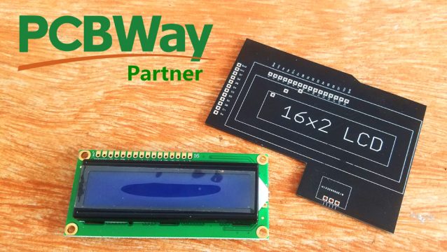
About the 16×2 LCD PCB board:
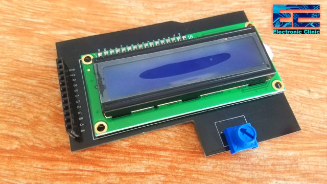
For the easy interfacing, I designed a PCB for the 16×2 LCD. This PCB is manufactured by the PCBway Company. As you can it looks amazing, now I can easily interface this LCD with the Arduino board using male to male type jumper wires.
4×4 Keypad and Electronic Lock Interfacing with Arduino:

All the connections are done as per the circuit diagram already explained. Now let’s have a look at the Arduino programming.
Password Door Lock Security System Arduino Code:
|
1 2 3 4 5 6 7 8 9 10 11 12 13 14 15 16 17 18 19 20 21 22 23 24 25 26 27 28 29 30 31 32 33 34 35 36 37 38 39 40 41 42 43 44 45 46 47 48 49 50 51 52 53 54 55 56 57 58 59 60 61 62 63 64 65 66 67 68 69 70 71 72 73 74 75 76 77 78 79 80 81 82 83 84 85 86 87 88 89 90 91 92 93 94 95 96 97 98 99 100 101 102 103 104 105 106 107 108 109 110 111 112 113 114 115 116 117 118 119 120 121 122 123 124 125 126 127 128 129 130 131 132 133 134 135 136 137 138 139 140 141 142 143 144 145 146 147 148 149 150 151 152 153 154 155 156 157 158 159 160 161 162 163 164 165 166 167 168 169 170 171 172 173 174 175 176 177 178 179 180 181 182 183 184 185 |
#include <Keypad.h> #include <LiquidCrystal.h> const byte ROWS = 4; //four rows const byte COLS = 3; //three columns char keys[ROWS][COLS] = { {'1','2','3'}, {'4','5','6'}, {'7','8','9'}, {'*','0','#'} }; byte rowPins[ROWS] = {A0, A1, A2, A3}; //connect to the row pinouts of the keypad byte colPins[COLS] = {A4, A5, 2}; //connect to the column pinouts of the keypad Keypad keypad = Keypad( makeKeymap(keys), rowPins, colPins, ROWS, COLS ); // 16x2 LCD #define rs 10 #define en 9 #define d4 6 #define d5 5 #define d6 4 #define d7 3 // initialize the library with the numbers of the interface pins LiquidCrystal lcd(rs, en, d4, d5, d6, d7); String password = "1234"; String mypassword; int redled = 12; int lock = 13; int counter = 0; int attempts = 0; int max_attempts = 3; void setup(){ Serial.begin(9600); // set up the LCD's number of columns and rows: lcd.begin(16, 2); pinMode(redled, OUTPUT); pinMode(lock, OUTPUT); digitalWrite(redled, LOW); digitalWrite(lock, LOW); Serial.println("enter password"); lcd.print("Enter Password:"); } void loop() { keypadfunction(); } void keypadfunction() { char key = keypad.getKey(); if (key){ Serial.println(key); counter = counter + 1; lcd.setCursor(counter, 1); lcd.print("*"); } if (key == '1') { mypassword = mypassword + 1; } if (key == '2') { mypassword = mypassword + 2; } if (key == '3') { mypassword = mypassword + 3; } if (key == '4') { mypassword = mypassword + 4; } if (key == '5') { mypassword = mypassword + 5; } if (key == '6') { mypassword = mypassword + 6; } if (key == '7') { mypassword = mypassword + 7; } if (key == '8') { mypassword = mypassword + 8; } if (key == '9') { mypassword = mypassword + 9; } if (key == '0') { mypassword = mypassword + 0; } if (key == '*') { Serial.println(mypassword); if ( password == mypassword ) { lcd.clear(); lcd.println("Welcome To"); lcd.setCursor(0,1); lcd.println("ElectroniClinic"); digitalWrite(lock, HIGH); delay(5000); digitalWrite(lock,LOW); mypassword = ""; counter = 0; lcd.clear(); lcd.setCursor(0,0); lcd.println("Enter password"); } else { Serial.println("wrong"); digitalWrite(lock, LOW); attempts = attempts + 1; if (attempts >= max_attempts ) { lcd.clear(); lcd.setCursor(0,0); lcd.print("Locked Out"); digitalWrite(redled, HIGH); delay(5000); digitalWrite(redled, LOW); attempts = 0; } mypassword = ""; counter = 0; lcd.clear(); lcd.setCursor(0,0); lcd.print("Wrong Password"); delay(1000); lcd.setCursor(0,1); lcd.print("max attempts 3"); delay(1000); lcd.clear(); lcd.println("Enter password"); lcd.setCursor(0,1); } } } |
Password Door Lock Security System Code Explanation:
#include <Keypad.h>
#include <LiquidCrystal.h>
I started off by adding libraries for the Keypad and 16×2 LCD.
const byte ROWS = 4; //four rows
const byte COLS = 3; //three columns
Next I defined the maximum number of rows and columns.
char keys[ROWS][COLS] = {
{‘1′,’2′,’3’},
{‘4′,’5′,’6’},
{‘7′,’8′,’9’},
{‘*’,’0′,’#’}
};
Then I defined a two dimensional array with keys information.
byte rowPins[ROWS] = {A0, A1, A2, A3}; //connect to the row pinouts of the keypad
byte colPins[COLS] = {A4, A5, 2}; //connect to the column pinouts of the keypad
The rows are connected with the Arduino’s Analog pins A0, A1, A2, and A3. While the columns are connected with A4, A5, and pin number 2.
// 16×2 LCD
#define rs 10
#define en 9
#define d4 6
#define d5 5
#define d6 4
#define d7 3
The RS pin of the LCD is connected with the Arduino’s pin number 10, EN pin is connected with pin number 9, d4 is connected with 6, d5 is connected with 5, d6 is connected with 4, and d7 pin of the LCD is connected with the Arduino’s pin number 3.
LiquidCrystal lcd(rs, en, d4, d5, d6, d7);
Initialize the library with the numbers of the interface pins
String password = “1234”;
The current password is 1234 which you can replace with any other password.
String mypassword;
The variable mypassword is used to store the password which is entered using the keypad.
int redled = 12;
int lock = 13;
An led is connected with the Arduino’s pin number 12 and the electronic lock is connected with the digital pin 13 of the Arduino.
int counter = 0;
Counter is a variable of the type integer and it is used to count the number of keys pressed, which helps me set the LCD cursor.
int attempts = 0;
int max_attempts = 3;
The variable attempts is used to store the number of wrong attempts, while the maximum number of wrong attempts is equal to 3.
void setup(){
Serial.begin(9600);
// set up the LCD’s number of columns and rows:
lcd.begin(16, 2);
pinMode(redled, OUTPUT);
pinMode(lock, OUTPUT);
digitalWrite(redled, LOW);
digitalWrite(lock, LOW);
Serial.println(“enter password”);
lcd.print(“Enter Password:”);
}
In the void setup function I activated the serial communication for the debugging purposes.
Set up the LCD’s number of columns and rows. The LED and electronic lock are set as the output using the pinMode() function. Turned OFF the led and electronic lock using the digitalWrite() function and finally, printed the Enter Password message on the LCD.
void loop()
{
keypadfunction();
}
Then starts the void loop function. As you can see the void loop function has only one function which is the keypadfunction().
Keypadfunction() is a user-defined function which has no return type and does not take any arguments as the input.
char key = keypad.getKey();
The getKey() function is used to read the pressed key and is stored in the variable key.
The following condition means if the key is pressed then simply send it to the Serial monitoring for the checking purposes, increment the counter by 1 and use the counter to update the cursor.
If 1 is pressed then add 1 to the mypassword, if 2 is pressed then add 2 to the mypassword, and so on for all the keys.
if (key){
Serial.println(key);
counter = counter + 1;
lcd.setCursor(counter, 1);
lcd.print(“*”);
}
if (key == ‘1’)
{
mypassword = mypassword + 1;
}
if (key == ‘2’)
{
mypassword = mypassword + 2;
}
if (key == ‘3’)
{
mypassword = mypassword + 3;
}
if (key == ‘4’)
{
mypassword = mypassword + 4;
}
if (key == ‘5’)
{
mypassword = mypassword + 5;
}
if (key == ‘6’)
{
mypassword = mypassword + 6;
}
if (key == ‘7’)
{
mypassword = mypassword + 7;
}
if (key == ‘8’)
{
mypassword = mypassword + 8;
}
if (key == ‘9’)
{
mypassword = mypassword + 9;
}
if (key == ‘0’)
{
mypassword = mypassword + 0;
}
Next we compare the password entered.
if (key == ‘*’)
{
Serial.println(mypassword);
if ( password == mypassword )
{
lcd.clear();
lcd.println(“Welcome To”);
lcd.setCursor(0,1);
lcd.println(“ElectroniClinic”);
digitalWrite(lock, HIGH);
delay(5000);
digitalWrite(lock,LOW);
mypassword = “”;
counter = 0;
lcd.clear();
lcd.setCursor(0,0);
lcd.println(“Enter password”);
}
If the asterisk key is pressed then compare the password entered with the pre-defined password. If both the passwords are same then print Welcome to electronic Clinic on the lcd, open the door, wait for 5 seconds and again close the door. Empty the mypassword and counter variables. Clear the LCD, Set the LCD cursor, and write Enter Password on the LCD.
else
{
Serial.println(“wrong”);
digitalWrite(lock, LOW);
attempts = attempts + 1;
if (attempts >= max_attempts )
{
lcd.clear();
lcd.setCursor(0,0);
lcd.print(“Locked Out”);
digitalWrite(redled, HIGH);
delay(5000);
digitalWrite(redled, LOW);
attempts = 0;
}
If a wrong password is entered, lock the door, means do nothing, increment the attempts, if the number of wrong attempts are greater than or equal to the value stored in the max_attempts variable then clear the LCD, type locked out on the LCD, turn ON the led for 5 seconds, and finally set attempts equal to zero.
mypassword = “”;
counter = 0;
lcd.clear();
lcd.setCursor(0,0);
lcd.print(“Wrong Password”);
delay(1000);
lcd.setCursor(0,1);
lcd.print(“max attempts 3”);
delay(1000);
lcd.clear();
lcd.println(“Enter password”);
lcd.setCursor(0,1);
And finally, some messages to the LCD which reminds you of the maximum wrong attempts.
For the practical demonstration watch video given below. Don’t forget to Subscriber to my Website and YouTube channel “Electronic Clinic”. Support my Website and channel by sharing articles and videos. If you have any questions regarding this project or any other project, let me know in a comment.
Watch Video Tutorial:
Related Project:
Arduino password security system, Enter a Password using only one button
Discover more from Electronic Clinic
Subscribe to get the latest posts sent to your email.


Thank you so much for this wonderful project I like it and I think it is the best tutorial I have seen up till now, their is only one thing I want to ask you . Is it possible to get redimate pcb for the lcd 16×2 because I could not find tutorial for it, if I could find a fully prepared pcb board for this project then it will be so much helpful. I appreciate your work, It has got quality. Great work…..???