Presettable Counters with Circuit Diagram in Digital Electronics
Last Updated on December 16, 2022 by Engr. Shahzada Fahad
Presettable Counters
A presettable counter is such a counter which counts up or down from a presettable value. In other words, a counter which has the capability of loading or pre-setting just one number, counting down or up from which is desired to be started, is called pre- settable counter (preset means setting a device on some value in advance or direct set). As the liberty or choice of loading any number higher than 0, rests with the user to decide as to from which particular number the up or down counting has to be started, therefore this counter is also known as a programmable counter. Thus, a presettable counter is a counter, in which counting starts from the value, which you load or enter into it, or the number, programming of which is done in it. These counters can either be synchronous or asynchronous.
In figure 8.14 (a), a presettable counter has been displayed, which consists of four JK flip-flops and due to it, it is also called a 4-bit pre-settable counter. This counter can count up or down any number between 0000 and 1111, which has been set via P0, P1, P2, P3. That’s any one number between 0000 to 1111 is programmed in counter via P0, P1, P2, P3 at the outset, as a result of which counter tends to set on this loaded or programmed number (as a result of an initial deliberate and intentional programming in the counter, this counter is known as a pre-settable counter) and starts counting from that number. If the logic diagram of this counter is analyzed, it becomes clear that when its load control line is dropped, the outputs of all AND gates associated with the line become high. As a result, clear and preset inputs of all flip-flops become inactive or disabled. In this case, this circuit counts in an upward direction and there is no effect of data inputs (P0 to P3) on the circuit.
Figure 8.14-A pre-settable counter
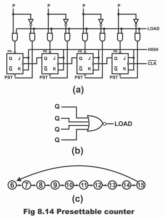
When LOAD line is high, data inputs and its complements pass through NAND gates and pre- set counter on P0, P1, P2, P3. (in figure PR implies pre-set whereas RST means re-set). For example, presume that preset input is as follows;
P0, P1, P2, P3 = 0 1 1 0
According to this input data, as P3 is low, therefore both corresponding NAND gates towards left of P3, produce a high preset and a low clear for Q3 flip-flop (remember that when both inputs of NAND gate are high, its output is low and when either one or both of its inputs are low, its output will be high). In this way, Q3 flip-flop clears and tends to reset (i.e. any binary bit stored previously within it, now becomes clear and 0 is stored in place of it). Similarly, as a result of a high (i.e. 1) P2 value, Q2 flip-flop sets and through a high P1 value, Q1 flip-flop sets. Whereas low bit on P0 (i.e. 0) clears Q0 flip-flop. As such, counter presets on the following value;
Q = 0 1 1 0 (decimal 6)
After presetting the counter on a specific number (i.e. 0110) when LOAD line is dropped or turned low once again, circuit starts to operate just like a normal counter and clock pulses being received continuously on which, produce following outputs turn by turn;
Q = 0 1 1 1 (decimal 7)
Q = 1 0 0 0 (decimal 8)
Q = 1 0 0 1 (decimal 9)
This output changes continuously with each clock pulse, until maximum count or highest binary number is received i.e.
Q = 1 1 1 1 (decimal 15)
After this, when next clock pulse strikes, counter becomes reset i.e.
Q = 0 0 0 0
Thus, in order to inculcate operation of a pre-settable counter, following points should be kept in mind as summary;
(1). When LOAD line is low, circuit counts
(2). When LOAD line is high, counter resets on P0, P1, P2, P3
(3). Preset means changing output from low state to a high state whereas reset means changing output from a high state to a low state. After programming the counter, it is up to you to decide whether to start counting from a down direction or in an up-direction.
The most important application of a pre-settable counter is its programming of a modulus. For this purpose, a NOR gate as shown in figure (b) is inducted with a pre – settable counter as illustrated by figure (a). In this way, Q outputs of pre-settable counter drive NOR gate, whereas NOR gate controls LOAD line of pre- settable counter. A NOR gate identifies and selects just one number, entire bits values of which are binary 0 and rejects all other numbers except this, therefore LOAD line is high when Q = 0000 and on all other numbers, LOAD line is low (remember that when all inputs of a NOR gate are low, its output is high at that time and when any one or both of its are high, its output becomes low). It means that when Q = 0000, the circuit becomes preset and when there is any other number from Q = 0001 to Q = 1111, circuit counts.
Suppose that if preset input is 0110, then continuous clock pulses 0111, 1000 and 1001 etc. received from clock, reach its maximum value during output process i.e.;
Q = 1 1 1 1
After this, when next clock pulse strikes, counter resets i.e. Q = 0 0 0 0
As soon as counter resets, NOR gate output turns out to be high immediately and data inputs preset counter on the following binary numbers;
Q = 0 1 1 0
In other words, counter reaches its preset value 0110 (decimal 6) by means of effectively jumping (i.e. blanking out or leaving) numbers from decimal 0 to decimal 5, as has been demonstrated in figure ©. As such, whatever value has been pre-set on the counter, counter re-starts counting from the preset value after reaching its highest or maximum value. That’s the reason it is called a pre-settable counter. These counters are available in TTL-IC form in the following numbers;
54 / 74161 synchronous binary counter operate in count-up mode
54 / 74163 synchronous binary counter operate in count-up mode
54 / 74191 + 54 /74193 4-bit synchronous binary counters operate in either a count-up or count-down mode
54 / 74160 + 54 / 74162 synchronous counters operate in count-up mode
54 / 74190 + 54/ / 74192 synchronous counters operate in either count-up or count-down mode
In figure 8.15 (a), TTL-IC of a 4-bit 54/ 74193 synchronous up-down binary counter has been illustrated. This counter comprises a master reset (MR) and that it can be reset on any desired count along parallel load inputs. PL pin drawn above IC is a control pin, which is used to load data to PA, PB, PC and PD pins. When the device is used as a counter, all these four pins are permitted as open pins, and control pin (PL) is turned high. Pin MR which is a master reset, tends to be low (remember that all flip-flops will get reset by means of providing a high level on MR).
There are two clock inputs CPU and CPD existing on this IC. When clock is connected with CPU input, the counter counts up and when clock is connected with CPD, the counter counts down as a result of this (i.e. it starts counting from 15 and continue counting up to 0). Remember that clock can be connected with any one of either CPU or CPD inputs at a time and both these inputs can never be connected together with clock. Moreover, unutilized input is being kept high. Counter outputs are QA, QB, QC, and QD. Two pins TCU and TCD as shown on output, are ten-count up and ten-count down pins respectively, which are used to drive or operate the instruments organized in a cascaded sequence (which is extensively used in digital volt meters and frequency counters etc.)
Figure 8.15-A 4-bit binary counter (presettable)
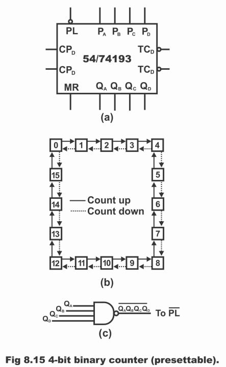
A 54 / 74193 counter is capable of undertaking a parallel-data-entry, by means of which numbers applied on a counter’s parallel data entry inputs (i.e. PA, PB, PC and PD) are reset. Whenever parallel load input (PL) is low, all data existing on these four inputs, shifts inside the counter. That’s counter resets on binary numbers provided via PA, PB, PC, PD.
Now by means of introducing a slight modification in the counter’s counting process, a NAND gate is also applied, which has the capability to sense any stable state (e.g. state 15 or 1111), which is then used to lower the gates’ output PL. Therefore, when QA, QB, QC, and QD are high or on state 15 (1111), at that time, only PL will be low. In such a situation, counter data will be preset on PA, PB, PC, PD.
For example, suppose that the values of parallel data entry inputs are as follows;
PA PB PC PD = 1001 (decimal number 9)
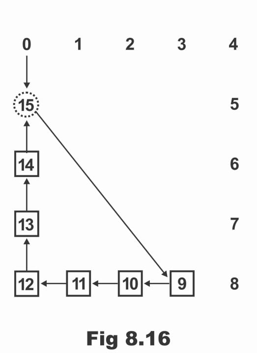
Thus, when a clock pulse is applied, the counter will no doubt count up to 15 (1111). After reaching decimal 15, PL will become low and number 9 (1001) will shift to the counter. Now, beginning from 9, counter will count 10, 11, 12, 13, 14 and up to 15 and completing the count, will preset on 9 (that’s start count again from 9).
This count sequence can easily be comprehended via a state diagram as shown in figure 8.16. It is obvious from the diagram that number 15 (or 1111) does not represent a stable state, rather it remains stable for a brief stint of time and during the meantime, counter presets. In this figure, stable states are 9,10, 11, 12, 13, and 14. In such a condition, it serves like mod-6 counters. It has to be inculcated that the procedure under discussion is an asynchronous one because this preset operation does not synchronize or harmonize with clock.
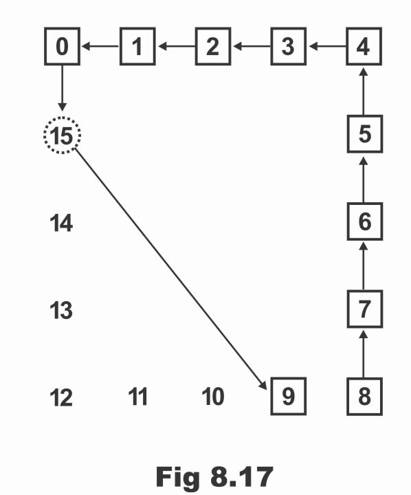
If clock is connected with count- down input, instead of count-up input of the counter (which has been discussed previously) and in case the counter is still preset on number 9 or 1001, then counter will reach 15 counting down from 9 (i.e. 8,7,6,5,4,3,2,1,0) and will preset again on 9 (i.e. after 15, it will get quickly back on number 9 and re -start a countdown). This has been illustrated in figure 8.17. In such a scenario, these counters are called a modulus-10 counters due to the fact that they contain ten stable states.
Figure 8.17
Previous Topic: Down Counters and Up-Down Counters in Digital Electronics
Next Topic: Types of Memories: Magnetic and Solid state Memory in Digital Electronics
For electronics and programming-related projects visit my YouTube channel.
Discover more from Electronic Clinic
Subscribe to get the latest posts sent to your email.


