Raspberry Pi Home Automation using RC522 RFID, Smart Home
Table of Contents
Description:
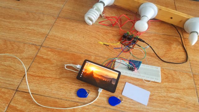
Raspberry Pi Home Automation- In this tutorial, you will learn how to make a Home or Office automation system using Raspberry Pi 3 b+, MFRC522 RFID reader, 5.5 inches Oled HDMI Touchscreen, RFID tags, and a 3 channel relay module. For the demonstration purposes, I have connected 220Vac light bulbs which of course you can replace with any other electrical loads which you want to control using the RFID tags. The whole system works perfectly, there is no false triggering and the load status is displayed on the 5.5-inch Oled Capacitive Touch Screen.
The Raspberry Pi Home Automation programming is done using the thonny IDE. This project can be easily modified, more relays can be connected which can be used to control the DC loads as well. This way you can make a smart home or office automation system. This project is entirely based on my previous tutorial, which covers the extreme basics, like for example
How to activate the SPI, How to download and install different packages for the MFRC522 RFID module, and how to write some basics python scripts for reading the tags. I highly recommend you should definitely read my previous article by clicking on the link given below.
Raspberry Pi RFID RC522 NFC Reader, Tags Scanner python code “https://www.electroniclinic.com/raspberry-pi-rfid-rc522-nfc-reader-tags-scanner-python-code/”
The components used in this project are sponsored by the DFrobot. DFrobot is a leading robotics and open source hardware provider. They create innovative, user-friendly hardware & software products that become the building blocks in all kinds of electronic projects. I personally recommend you should definitely visit www.dfrobot.com.
Caution! While everything is powered up, never touch the backside of the relay module as 220Vac can be really dangerous. I recommend you should wear protective gloves.
Without any further delay let’s get started!!!
DFrobot components purchase links:
Raspberry pi 3 b+: https://bit.ly/2QmJw6Y
Night Vision Camera: https://bit.ly/2q6R2bv
5.5 inch HDMI Oled capacitive Touchscreen: https://bit.ly/2Kq6OoP
Wireless Keyboard and Mouse Combo: https://bit.ly/2po2FKJ
Amazon Purchase links:
MFRC522 RFID module with tags:
12v SPDT type 4-channel relay Module:
Wireless Keyboard and Mouse for raspberry pi:
Night vision Camera for Raspberry Pi:
Oled HDMI touch display for raspberry pi:
Other Tools and Components:
Super Starter kit for Beginners
PCB small portable drill machines
*Please Note: These are affiliate links. I may make a commission if you buy the components through these links. I would appreciate your support in this way!
5.5-inch touch screen interfacing with Raspberry Pi:

The 5.5inch Oled touch screen is powered up using the Raspberry Pi USB port. The LCD is connected with the HDMI port of the Raspberry Pi using the HDMI Adaptor.
I have a very basic getting started tutorial in which you will learn how to connect a 5.5 inch HDMI Oled capacitive touch screen LCD, wifi keyboard, Mouse and a night vision camera with Raspberry pi 3 b+. This tutorial will help you with screen display resolution configuration.
RFID & Relay Module connection with Raspberry Pi:
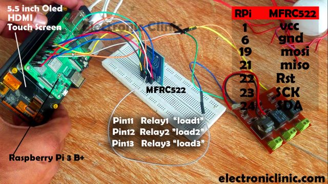
The MFRC522 RFID module connection with the Raspberry Pi is very simple. Pin number 1 of the Raspberry Pi which is the 3.3v pin is connected with the VCC pin of the MFRC522 RFID module, Pin number 6 is connected with the Ground, pin number 19 is connected with the mosi pin of the RC522 RFID module, pin number 21 of the Raspberry Pi is connected with the MISO pin of the RFID module, pin number 22 is connected with the RST pin of the RFID module, pin number 23 is connected with the SCK pin of the RFID module, and pin number 24 of the Raspberry Pi is connected with the SDA pin of the MFRC522 RFID module.
The 3 channel relay module is connected with the Raspberry Pi GPIO pins 11, 12, and 13. I designed this relay module, but if you want you can use a readymade relay module.
Relay Module Circuit Diagram:
This is the circuit diagram of the relay module used in this project, if in case you want to make your own relay module. All the relays used in this project are of the type SPDT 12V. Each relay is controlled using the driver which consists of the 2n2222 NPN transistor and a 10k ohm resistor. Pins 1 and 2 are the coil pins of the relays, while the remaining three pins of the relay are NO ”normally Open”, NC ”Normally Closed”, and C ”Common”.
One side of the relay coil is connected with the 12 volts while the other side of the relay coil is connected with collector of the 2n2222 NPN transistor. 1n4007 diodes are connected across the relay coil pins. These diodes are used against the back EMF protection.
Relay Interfacing with Raspberry Pi:
This is a 3 channel relay module that is powered up using a 12v adaptor. Three wires from the relay module are connected with the Raspberry pi GPIO Pins 11, 12, and 13 as already explained. Make sure you connect the relay module ground with the ground pin of the Raspberry Pi.
After you are done with all the connections, the next step is to start the programming.
Raspberry Pi Home Automation Python Code:
The Raspberry Pi Home Automation project is based on two programs. One program is written for reading the RFID tags and assigning the names. While the other program is written for controlling the loads. These programs are written in Thonny IDE.
|
1 2 3 4 5 6 7 8 9 10 11 12 13 14 |
import os import sys import RPi.GPIO as gpio from mfrc522 import SimpleMFRC522 import time CardWrite = SimpleMFRC522() try: text = input('Enter Data for Writing Card \t') print ('Place you Card to Write') CardWrite.write(text) print('Write Successfully') finally: gpio.cleanup() |
Run this program. write the name you want to assign to the RFID Tag, then hold the tag near the RFID reader. Repeat this for the remaining two tags. I assigned the names load1, load2, and load3.
|
1 2 3 4 5 6 7 8 9 10 11 12 13 14 15 16 17 18 19 20 21 22 23 24 25 26 27 28 29 30 31 32 33 34 35 36 37 38 39 40 41 42 43 44 45 46 47 48 49 50 51 52 53 54 55 56 57 58 59 |
import os import sys import RPi.GPIO as gpio from mfrc522 import SimpleMFRC522 import time CardRead = SimpleMFRC522() load1 = 11 load2 = 12 load3 = 13 gpio.setmode(gpio.BOARD) gpio.setwarnings(False) gpio.setup(load1,gpio.OUT) gpio.setup(load2,gpio.OUT) gpio.setup(load3,gpio.OUT) print ('Card Scanning') print ('for Cancel Press ctrl+c') try: while True: id, text = CardRead.read() print(id) print(text) if id == 284670566059: if gpio.input(load1): gpio.output(load1,gpio.LOW) print('Load1 Status OFF') time.sleep(1) else: gpio.output(load1,gpio.HIGH) print('Load1 Status ON') time.sleep(1) if id == 796101077: if gpio.input(load2): gpio.output(load2,gpio.LOW) print('Load2 Status OFF') time.sleep(1) else: gpio.output(load2,gpio.HIGH) print('Load2 Status ON') time.sleep(1) if id == 851563400170: if gpio.input(load3): gpio.output(load3,gpio.LOW) print('Load3 Status OFF') time.sleep(1) else: gpio.output(load3,gpio.HIGH) print('Load3 Status ON') time.sleep(1) except KeyboardInterrupt: gpio.cleanup() |
After I was done with the programming, first I checked my programming on LEDs, I was able to control the LEDs using the RFID Tags.
After I was satisfied with the programming, then I connected the relay module and 220Vac Bulbs. I successfully controlled all three bulbs. With this my Raspberry Pi Home Automation project comes to an end. If you have any questions let me know in a comment. For the practical demonstration watch video given below.
Don’t forget to Subscriber to my website and YouTube channel.
Related project:
https://programmingdigest.com/raspberry-pi-hmi-project-using-pyqt5-software-tutorial/
Watch Video Tutorial:
