Reed Switch working, Reed Switch based Projects, Reed Switch use with Arduino
Last Updated on August 17, 2024 by Engr. Shahzada Fahad
Table of Contents
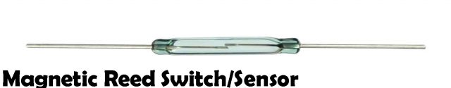
Reed Switch:
Reed switch was invented in 1936 Walter B. Ellwood in the bell telephone labs. Reed switch consist of pair of ferromagnetic flexible metal contacts nickel or iron which is easily magnetize and demagnetize. A reed switch a very low resistance when close typically 50mΩ. It requires zero power to operate.
The relative stiffness of the reed blades along with the small gap and overlap between the two contacts controls the sensitivity of the reed switch. The sensitivity of the switch is the amount of magnetic field that is required to actuate the contact an open or closed mode. It is measured in units of ampere-turns (AT). Most reed switches have a sensitivity range of 10–30 AT, where 10 AT is more sensitive than 30 AT.
Reed switches feature incredibly high reliability for a mechanical switch, and they are able to function for billions of cycles before failing. Additionally, because of their sealed construction, they can operate in explosive environments where a spark could potentially have disastrous results. Reed switches may be an older technology, but they are far from obsolete.
Amazon Purchase Links:
Arduino Nano USB-C Type (Recommended)
*Disclosure: These are affiliate links. As an Amazon Associate I earn from qualifying purchases.
How Does a Reed Switch Work?
The switching mechanism is comprised of two contacts of ferromagnetic blades inside in the glass separated by only a few microns. These contacts are normally open when a magnet approaches these blades; the two blades pull toward one another. There is no air in the glass, they are hermetically sealed in the glass.
The reed switch operated in the presence of the magnet. Once touching, the blades close the normally open (NO) contacts, allowing electricity to flow if we want to check it’s working we will check it with digital multimeter we will connect one terminal of the reed switch is connected with one probe of the multimeter and other terminals of the reed switch is connected with the other probe of the multimeter and set multimeter on beep as the reed switch as normally open so we will not hear any beep when we bring a magnet near to the contacts a magnetic force will be generated and the contacts of the reed switch will be magnetically polarized and these contacts will touch each other and beep in the multimeter will start. Some reed switches also contain a non-ferromagnetic contact, which forms a normally closed (NC) output. An approaching magnet will disconnect the contact and pull away from the switching contact.
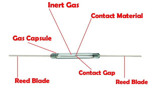
Reed Switch Construction:
Contacts are constructed from a variety of metals including nickel, rhodium and tungsten are used due to its high melting point. Some varieties even use mercury, which must be kept in the proper orientation to switch correctly. The switch material of the reed switch is made up of ferromagnetic material which is elastic it will push when the magnet is bring near it. The switch blades are sealed in glass envelopes filled with inert gas commonly nitrogen seals or vacuum in case of high voltages in order to give it long life the contacts at an internal pressure less than one atmosphere. Sealing isolates the contacts, these contacts are usually electroplated in a vacuum which prevents corrosion and any sparks that might result from contact movement.
Types of Reed Switches:
Single pole, single throw, normally open (SPST-NO)
Single pole, single throw, normally closed (SPST-NC)
Single pole, double-throw (SPDT)
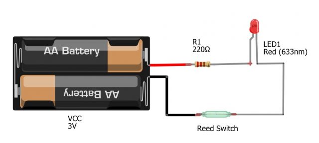
Reed Switch with the led:
Connect a reed switch one terminal with the battery and other terminals with the cathode of the led. Connect the one terminal of the resistor with the anode of the led and other terminals of the resistor with the battery. Now when we will bring a magnet near the reed switch the contacts of the reed switch will be close and the led will ON. When we remove the magnet the contact will separate and the LED will OFF.
Reed Relay:
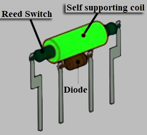
To make reed relay we will make turns of copper wire over the reed switch. So that when the current will flow through the coil it will work as a magnet. In reed relay magnetic field is generate by the electric current flowing through an operating coil which is fitted over on one or more reed switches. The current flowing in the coil operates the reed switch. The coil has hundreds of turns when the operating voltage is applied to the coil a magnetic field is generated which in turn closes the switch in the same way as in the reed switch in which we need to bring the magnet near it. Reed relay operate without the permanent magnet. Its operating speed is high as it is small, lightweight, require very less operating power and have lower contact capacitance. There current handling capacity is limited but with the appropriated contact material it is suitable for dry switching application. They are mechanically simple of high operating speed. It is highly reliable and has long life. Millions of reed switches were used in telephone exchanges in the year 1970.
In the below diagram we have reed relay in which there is reed switch inside it. Coil is rapped on the reed switch. There is diode with the reed switch which will suppress any back emf. The reed relay package consist of four pins in which the end pins are the reed switch pins and the middle two pin are the diode pins. A mu metal screen is added to the encapsulating shell to reduce the magnetic interaction between parts.
The mechanical motion of the reed is below the fatigue limit of the material so the reeds do not break due to fatigue. Wear and life are almost entirely dependent on the electrical load effect on the contacts along with the material of the reed switch. Contact surface wear occur only when the switch contacts open or close because of this manufacturer’s rate life in number of operations rather than hours or years.
Higher voltages or higher currents have faster wear and shorter life. The glass envelop extends their shorter life and can be damaged if the reed switch is subject to mechanical stress. They are cheap, durable and can last for about billion actuations.
Areas of Applications:
- Burglar alarm system for the doors and windows
- Laptops: reed switch put your laptop to sleep/hibernate when the lid is closed
- Fluid level sensors: In a tank a floating magnet is used to activate the switch placed at various levels
- Speed sensor: In bicycle wheels and dc motors
- Dishwashers: In the spinning arms of dishwashers
- Washing machine: They keep your washing machine from running when the lid is open
- Thermal cut-offs: In the thermal cut off in the electric showers, to stop the water heating to dangerous levels
- Cars: Reed switches are used in cars to know whether the car has enough brake fluid and whether or not your seat belt is fastened
- Reed switches are also in the applications which make use of their extremely low leakage of current
- Anemometers with rotating cups have reed switches inside that measure the speed of the wind
- Reed switches are used in old keyboards, vehicles, industrial system, household appliances, telecommunication, medical appliance, clam shell phones
Advantages of using a reed switch
Reed sensors have many advantages some of which are given below:
- No supply of voltage – as they are triggered by magnetism it will work when the magnet will brought near it, there is no voltage required.
- Compact – reed switches are incredibly compact compared to mechanical switches
- No mechanical wear: because there is no physical pressure applied to the switch, there are no mechanical wear and tear.
- Atmospheric corrosion – there is vacuum or nitrogen gas inside it also as the contacts of a reed switch are sealed within a glass tube they are protected from atmospheric corrosion.
Reed Magnetic Switch Door / Window Security:
Components Required:
- Reed switch
- Resistor 100kΩ, 680Ω
- Led
- 2 BC547 transistors
- 22µF capacitor
- Buzzer
- 9V Battery
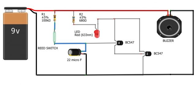
Circuit Explanation:
One terminal of 100KΩ resistor is connected with the positive terminal of the battery the other terminal of the resistor is connected with the reed switch terminal the other terminal of the reed switch is connected with the 22µF capacitor positive terminal and the negative terminal of the capacitor is connected with the ground. One terminal of the 680Ω resistor is connected with the positive terminal of the battery the other end of the resistor is connected with the led. The collector of the BC547 transistor is connected with the cathode of the led. Base of the transistor is connected with the positive terminal of the capacitor. The emitter of the transistor is connected with the base of the other transistor. The emitter is connected with the ground. The positive terminal of the buzzer is connected with the positive terminal of the battery and negative terminal of the buzzer is connected with the collector of the first transistor.
This circuit can be used for door security. It should be fitted on the door with the magnet. When the magnet will bring near the reed switch the switch will be closed and the buzzer will start when the magnet will be removed the reed switch will be open and the buzzer will stop.
Features and Benefits:
- No physical contact is required to operate the switch
- Zero power required for switch actuation
- Reed switch can operate in both hot and cold temperatures
Water Softener levels in dishwasher controlled by Reed switch:
A critical function is the rotation of the spray arm for cleaning the dishes and utensils. Many machines have spray arms on both the topside and bottom side of the wash compartment. The hot and cold water pressure propelled the spray arms. Some higher-end machines have motor-driven spray arms. It is important that the spray arm does not become obstructed by misplaced dishes or utensils within the washer baskets. If the arm does become blocked, the spray arm only sprays the dishes at that position, while another negative effect is that the motor could burn out because the stoppage causing a higher current draw. The ultimate results are that the dishes are not as clean as desired. The spray arm used the reed sensor and magnet in the continuous movement.
A magnet is mounted to the rotating arm while the sensor is mounted within the body or frame of the machine.
When the spray arm rotates normally, the magnet passes under the reed switch and the magnetic field actuates the reed switch contacts. The contact re-opens after the magnet passes by the sensor. If an obstruction of the spray arm occurs mean that the switch will be break the magnet no longer activates the reed switch. The microprocessor detects this non-activation; either stops the machine or activates an alarm or light on the dishwasher. Once the obstruction is removed, the dishwasher then operates normally.
The reed switch is perfect for this wet environment because of the precious metal contacts are contained within a hermetically sealed glass capsule. Moisture and fluctuating temperatures do not affect the reliable operation of the reed switch.
A magnet is generally imbedded in a float that rises and falls with the amount of water softener fluid. A reed sensor is mounted in the chassis of the dishwasher on a PCB. When the level of fluid drops the reed sensor is strategically placed to energize. When this happens a light on the outside panel will begin to flash and a beeper begins to alert the user that they must fill the water softener fluid reservoir. The dishwasher will resume its normal process when the user fills the reservoir. The water and stream spray will be experience by the reed sensor in this application including the high and low temperatures, all of which exist on the interior of the dishwasher. The reed sensor is an excellent choice it is packed in glass due to which it can operate reliably over a wide temperature range, and represents an economical way to carry out the sensing function.
Features
- Magnet and Reed Sensor are isolated and have no physical contact by typically having the magnet mounted to a rotating disk, and the Reed Sensors are mounted strategically to a PCB, such that the magnetic field of the magnet will be sensed with each rotation of the disk.
- The reed switch used in the Reed Sensors is hermetically sealed and is therefore not sensitive to its surrounding environment
- The magnet is not affected by high and low-temperature environments
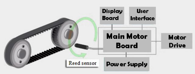
Speed Sensing Using Reed Sensors
Reed switch-based sensors are used as highly effective speed sensors in low cycle rate applications with rates up to a few thousand revolutions per minute (RPM). For example, in treadmills, a reed sensor is used to detect the speed of the moving
Belt. Two permanent magnets are placed on diametrically opposite ends of the belt
Pulley, and a reed sensor is mounted to the treadmill frame perpendicular to one end of the pulley. As the treadmill pulley rotates, when the reed switch will be near with the magnet the circuit will be activated and when the magnet move away from the reed sensor circuit will be deactivated which will show us the speed when it complete one revolution. The time interval between the detection of each magnet is used to compute the speed at which the pulley is rotating. Reed sensors are highly accurate in speed sensing applications where there is a rotating part. They are commonly used in fitness equipment where there is a rotating part with a variable speed.
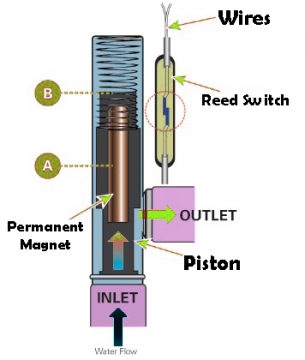
Reed switch in instant geysers:
A flow switch utilizes a reed switch to detect the motion of a valve, paddle wheel or piston that is fitted with a permanent magnet. This type of technology is usually use in the instant geysers. For example, in some tankless water heater units, the flow sensor contains a permanent magnet that is fixed to a piston that is loaded with the spring. It will move when there is water pressure present in the system. As the water pressure increases, the piston movement brings the magnet into the proximity of the reed switch. This causes the reed switch to close and signals the presence of water flow.
A flow sensor utilizes a turbine with an attached magnet that rotates by a fixed
reed switch. The speed at which the turbine rotates is proportional to the flow rate of the fluid. When there will be no flow of water the magnet will be at position A and when user open the tap water will start to flow pushing the magnet to position B.
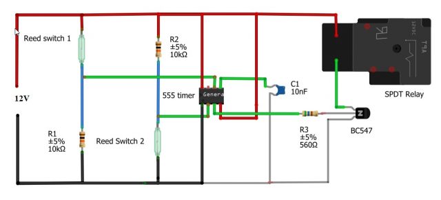
Automatic Water Refiller for Air-Coolers:
Air-coolers provide cool air in a room by adding moisture to the air. In water air cooler there is a dc motor which will be used to move water. The fan air absorb moisture from the water this air is blown in the room by fan, which makes the room temperature drop. These coolers require frequent refilling of water. When the level of the water will be drop from certain level it will be automatically refill by using the circuit.
Components Required
- 2 Reed switches
- 10KΩ Resistor
- 560Ω Resistor
- 555 timer
- BC547 transistor
- 10nF Capacitor
- Spdt Relay
Circuit and working:
We are using two reed switches in this circuit. We will connect one terminal of the reed switch with the positive terminal of the battery and other terminal of the reed switch with the 10kΩ resistor and connect it with the pin number 6 of the 555 timer. Connect the other terminal of the resistor with the ground. Now connect another 10kΩ resistor with the positive terminal and connect reed switch with the other terminal of the resistor with the reed switch and connect it with the pin number 2 of the 555 timer. Connect the other terminal of the reed switch with the ground. Connect pin number 4 and 8 of the 555 timer with the positive terminal of the battery. Connect 0.01µF capacitor with the pin number 5 of the 555 timer. Connect 560Ω resistor with the pin number three of 555 timer and then connect it with the base of BC547 transistor. The emitter of the transistor is connect with the ground and collector of the transistor is connected with the one coil of the relay and other coil of the relay is connected with the positive terminal of the battery. We can connect dc motor with the relay.
555 timer IC is configured similar to bi-stable mode, the only difference being that switch S1 is connected to pin 6 instead of pin 4.
The two reed switches (S1 and S2) are affixed at upper and bottom levels of the tank. The working of the circuit is pretty simple.
If water drops below the predetermined level, the magnetic float closes reed switch S2 to pull pin 2 of 555 timer to ground. Thereby the voltage on pin 2 goes below 1/3Vcc and the output of 555 timer goes high. This energizes the relay to activate the solenoid valve. Thus the water flows into the tank.
When the tank is full, the magnetic float closes reed switch S1. Pin 6 of 555 timer goes above 2/3Vcc and the output goes low. This de-energizes the relay to deactivate the solenoid valve, which stops the water flowing into the cooler tank.
The water tank of an air-cooler has two holes drain outlet and overflow outlet. Level-sensing arrangement for the water tank is done as follows: Attach a small-diameter PVC pipe to the tank between the two outlets. Put a magnetic float inside the PVC pipe. Affix one reed switch on the pipe near the drain outlet and the other reed switch near the overflow outlet.
The magnetic float can be made using a small speaker magnet and a hollow float ball. The diameter of the magnetic float should be slightly less than the PVC pipe’s so that it can float freely from bottom to top, or vice versa, based on the water level. If possible, fit the pipe in the tank’s inner wall with reed switches affixed externally.

Theft alarm circuit using reed sensor:
Components Required:
- 10KΩ Resistor
- 75KΩ Resistor
- 1KΩ Resistor
- Reed switch
- 555 timer
- 1µF capacitor
- 47nF capacitor
- Buzzer
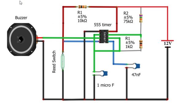
Connect one terminal of 15KΩ resistor with the reed switch. Connect the other terminal of the reed switch with the ground. Connect the 75KΩ resistor with the positive terminal of the battery and other terminal with the pin number 7. Connect the pin number 8 of the 555 timer with the positive terminal of the battery and connect pin number with the ground. Connect 1µF capacitor at pin number 6 and connect the other terminal of the capacitor with the ground. Connect 47nF capacitor with the pin number 6 and connect the other terminal with the ground. Connect 1KΩ resistor between pin number 6 and 7. Connect pin number 4 with the reed switch. Connect the positive terminal of the buzzer at pin 3 and other terminal with the ground.
WORKING OF THEFT ALARM CIRCUIT:
555 timer lies in the heart of this circuit. Here it is responsible for generating pulse to drive the buzzer. The 555 IC is wired as an astable multivibrator but with teeny tiny modification to make it work as a burglar alarm. Usually for astable multivibrator using 555 IC 4th pin ( reset ) is connected to Vcc but in here we have connected a reed switch to it. Reed switch is just like a normal switch but the difference is that reed switch gets closed only under the influence of a magnet and cannot be operated manually. When a magnet gets near a reed switch, it closes the connection and current flow occurs through it. But when magnet moves away it breaks the connection and current ceases to flow.
When the reed switch is closed the reset pin will be grounded. This means that 555 timer will not produce any output pulse in the output. As a result buzzer will be turned off. When we move the magnet away from the reed switch; the switch opens. This forces 4th pin ( reset ) to connect with Vcc. This in turn will completes the astable circuit and output pulse of steady frequency will be generated in the 3rd pin of 555 IC. This will be then fed to buzzer which acts as a sounding element or in words as an alarm.
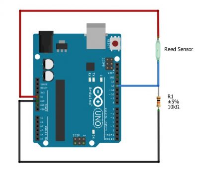
Arduino with Reed switch:
In this circuit we will use Arduino with reed switch. Connect one terminal of the reed switch with 5V and other terminal with the pin number 12. Connect 10KΩ resistor with the reed switch and connect other terminal of the resistor with the ground.
Code:
|
1 2 3 4 5 6 7 8 9 10 11 12 13 14 15 16 17 18 19 20 21 22 23 24 25 26 27 28 29 30 31 32 33 34 35 36 37 38 39 40 41 |
#define reedPin 12 #define led 13 int reedState = 0; void setup() { pinMode(led, OUTPUT); pinMode(reedPin, INPUT); Serial.begin(9600); } void loop() { reedState = digitalRead(reedPin); if (reedState == HIGH){ Serial.println("reed switch ON"); digitalWrite(led, HIGH); } else{ Serial.println("reed switch OFF"); digitalWrite(led, LOW); } delay(500); } |
We have define the 13 number pin of the Arduino as output and 12 number pin as input. When we will bring magnet near the reed switch the switch will close and the led in the Arduino will blink also we can see on serial monitor a message will display that reed switch on and when we remove the magnet the switch will be open and led will off and on serial monitor a message will display that reed switch off.
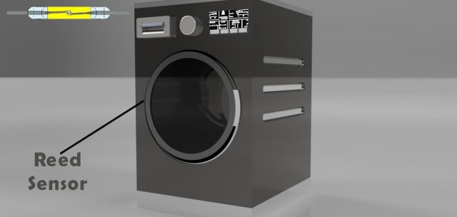
Reed Switch in Washing machine:
In the former of the two rotating directions, opening the top can be very dangerous if the drum continues to rotate. In automatic washing machine the reed switch is used when we open the door of the washing machine the machine will be off because the reed switch is de-energized
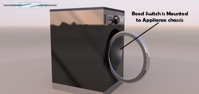
When we close the door the reed relay will be energized and the washing machine will be turn on.
Automatic Car Roof:
The car roof can be open and close with the help of reed relay. In this process we used two reed relays when the button will be energized the reed switch connected with the motor will be energized and the roof will start to close.
Mobile phones:
The folding mobile phone turn on and off with the reed switches on and off when we open or close the phone. It has a normally closed reed switch in the lower part of its body where the keypad is located and a magnet in the upper part where the screen is located. The magnet and the reed switch are far apart when the phone is open. The contacts on the reed switch are pushed together and the power flows through the phone. When we folding the mobile the magnet in the upper part of the mobile moves toward the reed sensor. As the switch we are using is normally closed so when we close the mobile the switch will be opened and the power will be off.
For video tutorials visit My Youtube channel.
Discover more from Electronic Clinic
Subscribe to get the latest posts sent to your email.


