Schmitt trigger Op Amp Circuit Working, Calculation, & Use
Last Updated on September 12, 2021 by Engr. Shahzada Fahad
Table of Contents
Schmitt trigger:
The Schmitt trigger is actually a comparator circuit but there something extra added to the Schmitt trigger which makes it different from all the comparators. It is also known as regenerative comparator. In comparator we have some input signal and threshold value. The Schmitt trigger is also known as 1 bit quantizer because it converts the analogue signal in to digital signal. The input signal will be compare with the threshold value and the comparison will gives us either high or low value like we will get a square wave which is basic working of any comparator. The same thing is happening with the op amp circuits, in Schmitt trigger we do not have one threshold value. We have two threshold values in the Schmitt trigger and these two threshold values will help us in understanding when and how the high to low and low to high transition occurs specifically. There is specific upper and lower threshold and due to this upper and lower threshold values. The signal has to be exactly a dap level or greater to that a transition have to happen. So the main advantage of the Schmitt trigger is that it has two threshold values in which the input signal will not be compared with one threshold so the input signal will not just compared with one threshold to get the square wave and the square transition will depend upon whether the input is greater or less than input value. As in the Schmitt trigger we have two threshold values which are upper threshold value (VUT) and lower threshold value (VLT). So it will prevent the unnecessary transition created by the noises. We know that there will be not just input signal but there will be also noise or noise signal will come to the input signal. Due to which unnecessary transition will be created. The Schmitt trigger can function as latch or flip flop (bi-stable multivibrator). It is possible to interconvert a latch and schmitt trigger in to each other.
Calculation of the values:
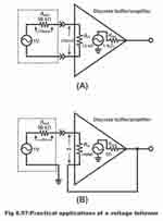
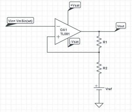
Schmitt trigger has inverting amplifier actually in which we have inverting and non-inverting terminals. The input is connected at the inverted terminal and there is positive feedback connected to the non-inverting terminal and to there is reference signal. Generally this reference voltage should be kept to 5V or up to the VCC of the operational amplifier.
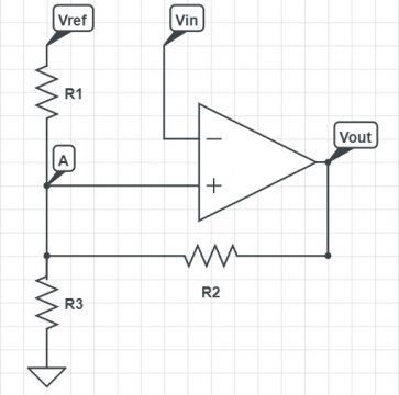
But if we closely examine the threshold value or the voltage coming to the non-inverting terminal is not actually 5V but this is the voltage at the specific point which is taken as point A. The node voltage at the point A is given to the non-inverting terminal so that voltage is taken by the comparator or op amp for comparison. The voltage at point will be taken as the threshold voltage for the comparison and not the value given at reference. The value of this voltage will depend on as there is feedback connected from the output which is positive feedback. The voltage at the point “A” will depend on the output voltage and the values of the resistances. There is actually voltage division happening and the resulting and the resultant of this voltage division is the voltage coming at the node “A” and that voltage is taken by the Schmitt trigger for comparison. The output of the Schmitt trigger will be either 0V or 5V. The 5V represent high voltage while 0 V represents low voltage. The voltage coming to the node A will vary and hence we will get two values for voltage at A when the output voltage is 0V and from the output voltage to be 5V. So these two voltages are called upper threshold voltage and lower threshold voltage. The Schmitt trigger implements hysteresis. Hysteresis is basically the dependence on the state of the system on it history which means the history output. The past outputs which are connected through feedback to the input terminal. In simple words we can say that for Schmitt trigger the threshold voltage or the input is depending on the history or the past outputs and this dependence is implemented with the help of positive feedback.
If we are giving analogue signal at the input side of the Schmitt trigger we will get square wave or a digital waveform. Suppose we have an analogue signal in which the dotted lines represent the upper threshold and the lower threshold. When the signal is passing through the upper threshold the output will be dropping suddenly to zero volt means the output will go from high to low. When the signal is crossing the lower threshold value then the output value will go from low to high. We will have two output values either at will be 5V or 0V.
Now we will calculate the threshold value let us consider that we are giving 5V as a reference voltage at the input. Consider that the output voltage generated is zero volt. When the output voltage is 0V then the resistance R2 and R3 are connected to the ground and R1 is connected to the reference voltage. This is actually voltage division circuitry.
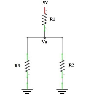
Now by applying the voltage division rule when the Vout = 0 This will be the lower threshold value.
VA = (R2 || R3 /R1 + R2 || R3) * Vref
When the voltage will be 5V so for that case when the R2 will be connected to 5V and R1 will also be connected to 5V and R3 will be connected with the ground. This will give us the upper threshold voltage value.
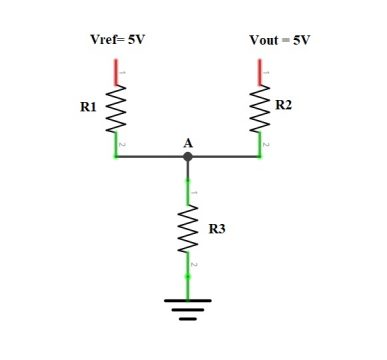
Depending upon the output voltage value we will get two different threshold values.
Why we use Schmitt trigger?
We have two inputs and one output in the comparator if we put a potentiometer at the negative terminal of the comparator we can change the threshold value for the signal as the output will pass too high or too low we can lower or increase this threshold with the help of potentiometer. Let suppose that we put a threshold of 3V using the potentiometer.
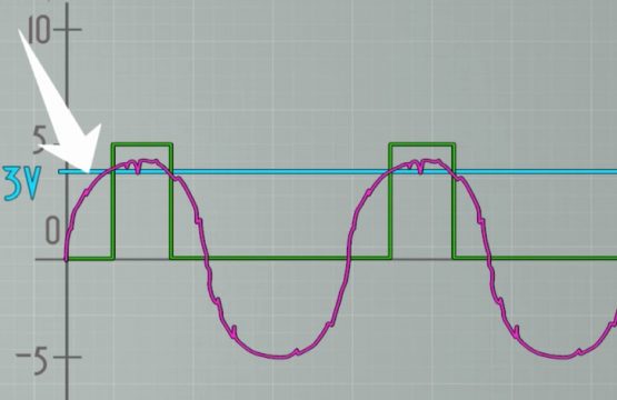
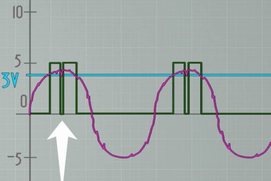
Now at the positive input we have a signal that oscillates and we want to read that so we want each oscillation becomes a square wave. Each time the input is higher than 3 V. We will have high pulse at the output. When we have a noise at the input let us consider the same signal but have some noise. After the signal passes through the 3V we have a little bit of noise and a small ripple that goes below 3V that will result in the short low pulse at the output which would be an error since we do not want that so that is why we use the Schmitt trigger.
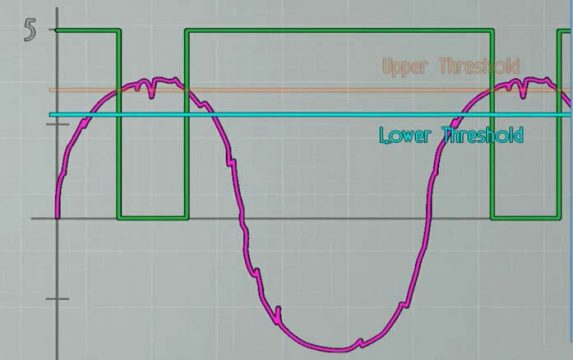
Because it has two threshold values one for the rising edge and one for the falling edge. Let we will see the same signal but at the two threshold values. When the input gets over 3V the output will be high if want the signal to be high pulse just invert the signal two times. So then the input has the ripple and gets a little bit bellow 3V but since it did not pass below the second the second threshold the output will not change. Thus we will obtain a signal which we want this is the main function of the Schmitt trigger to convert a noisy signal in to a good square signal that could be than read by the microcontroller or other digital components .
Schmitt trigger working:
Now let us consider a Schmitt trigger in which we are using the positive have positive feedback. When it was open loop it was comparator in which the output will be whether positive Vsat or negative Vsat. In this circuit we have open loop gain is infinity and also Rin value in infinity.
Vf Represents the feedback voltage
Vin= Input voltage
VI= Inverting voltage
VNI= Non Inverting voltage
AOL= Open loop gain
Vout = AOL *(VNI – VI)
As the open loop gain is infinity so the equation will become:
Vout = ͚ * (VNI – VI)
When the value it non inverting terminal is maximum then inverting terminal value
VNI > VI
Then the output value will be positive Vsat.
When the value it non inverting terminal is minimum then inverting terminal value
VNI > VI
Then the output value will be negative Vsat.
To find the feedback voltage we will apply the KCL law:
Vf – Vout / R1 + (Vf – Vref /R2 ) + 0 = 0
Vf/R1 – Vout/R1 + Vf/R2 – Vref /R2 = 0
Now by rearranging the equations we get:
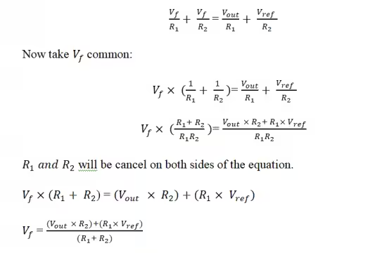
The feedback voltage is equal to the non-inverting voltage .
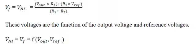
The resistance values are constant which will not be changing; also the reference voltage which is dc voltage will also be constant. So there will be only change in the output voltage which is:
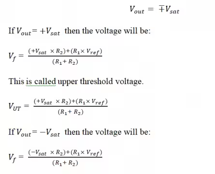
This is called lower threshold voltage.
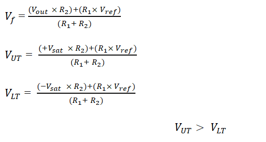
VLT = ((-Vsat × R2)+(R1×Vref))/((R1+ R2))
There will be two types of voltage at the non-inverting terminal which are upper threshold voltage and lower threshold voltage.
Condition for Schmitt trigger:
There is condition for Schmitt which should be satisfied for designing the Schmitt trigger.
|R1×Vref| > |R2× Vsat|
This means that the upper threshold voltage and lower threshold voltage both number will be positive.
The second condition is that the saturation voltage will be greater than the reference voltage.
|Vsat| > |Vref|
Case 1:
When the reference voltage is positive the feedback voltage be:
Suppose that the input voltage is VIN= 5sinωt so the VM=5V and we consider the upper threshold voltage is 3V and the lower threshold voltage is 1V. If V(out )=+VSat then Vf= VUT
V(out )=-VSat then Vf= VLT = 1V
Schmitt trigger using 555 timer:
In this circuit we will connect some external components with the 555 timer so that it will work like Schmitt in which we will generate square wave from sinusoidal wave.
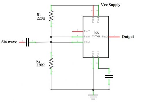
The first pin of the 555 timer is connected to the ground. Connect the 2 and 6 pin together. The second pin is called trigger pin and the 6 pin is called threshold pin and are connected with R2with the ground. Pin number will be used for reset. If we want to reset we will give negative pulse and if does not want the timer to reset connect the 4 pin with the Vcc. Pin number 5 is control pin and it control the output pulse width and is grounded through capacitor in order to reduce noise. The pin number 7 is discharge pin and nothing is connected with it. pin number 8 is supply pin which is connected with the Vcc. The pin number 6 and 7 is connected with the capacitor and sinusoidal signal is applied through this capacitor which will allow ac and block dc. The R1 and R2 value should be kept equal.
The capacitor is coupling capacitor so for AC analysis capacitor will be short circuit. So voltage and current will be connected directly. For dc analysis it will be open circuit. So when the capacitor is open circuit so the voltage at pin 2 and 6 will be equal to:
V2= V6= Vcc/2
Whenever we apply sinusoidal signal the capacitor behave short circuit which will couple the sinusoidal signal or AC signal across the 2 and 6 terminals. So the voltage will become:
V2= V6= Vcc/2 + Vi
When the V2 and V6 are greater then 2/3 Vcc. When the V2 is greater then 2/3 V_cc then it will be +Vsat and it will become logic 1. When the V6 is greater then 2/3 Vcc then it will be -Vsat and it will become logic 0. In this way we will obtain a square wave.
Application of Schmitt trigger:
Schmitt Trigger devices find applications in:
- Signal conditioning means it will convert the noisy signal in to square wave without any noise.
- Schmitt trigger are used in oscillator as closed loop negative feedback configurations
- The Schmitt trigger can be used to Switching power supplies and function generators.
Discover more from Electronic Clinic
Subscribe to get the latest posts sent to your email.