Single Phase Induction Motor Construction, Working, and Types
Table of Contents
Introduction to single phase induction motor:-
Single Phase Induction Motor Construction and Working– A single-phase induction motor (SPIM) is one of the most widely used types of low power ac motors, especially for domestic or commercial applications where a three phase power source is not available. Such motor has both main and auxiliary winding for starting torque. In general the, auxiliary winding is only used for producing the starting torque, hence the Single Phase Induction Motor SPIM has the pulsating torque due to the excitation of only main winding. In most of the applications the Single Phase Induction Motor SPIM usually runs at fixed speed. In this case, the efficiency and the power factor of motor drive are very low. The single-phase induction motor is the most frequently used motor for refrigerators, washing machines, clocks, drills, compressors, pumps, and so forth .
Control point of view
The induction motors are nonlinear, high-order dynamic systems of considerable complexity. They are amenable to a formal mathematical analysis. However it is not a trivial matter to comprehend the principles of their operation in an imaginative way especially under transient conditions. Conversely, induction motors are widely used in practical systems because of their simple construction, low maintenance requirements, and lower cost compared with other types of motors such as brushless DC motors. Therefore, it is a great significance to investigate the control problems of induction motors
With the development of power electronic technology, control technology and control theory, a variety of general and high performance control strategies have been born and become more and more mature, some representative control strategies of the induction motor are as follows: speed opened-loop constant V/f control, field oriented vector control (FOC), direct torque control (DTC), feedback linearization control, sliding mode control (SMC), intelligent control etc. These strategies have different advantages and disadvantages hence these strategies must be selected appropriately according to the specific requirements in practice. Traditional vector control methods depend on PI regulator and the parameters of the regulator are difficult to regulate. Though some new methods have good dynamic and static performance but their algorithms are complex and have many parameters to regulate. Introduced in the last decades, synergetic control has rapidly gained acceptance not only by the robust control but also by the industrial partners as illustrated by its implementation in power electronics field. The good robustness of the new control theory provides a new train of thoughts of motor speed control.
Construction of single phase induction motor:-
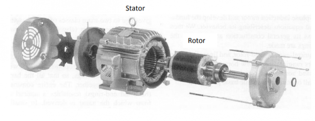
The single phase induction motor consist of two parts
- Stator
- Rotor
The stators are separated from rotors by small air gap have ranges from 0.4 mm to 4 mm depends to size of motor.
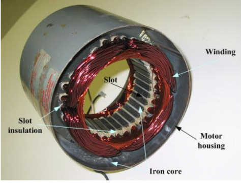
Stator
The stator is the stationary section which is built up of high grade alloy steel laminations to decrease the eddy current losses. The laminations are slotted on the inner side and are insulated from each other. These laminations are supported in a frame of stator of cast iron or fabricated steel plate. The stator insulated conductors are placed in these slots. These stator conductors are connected to form a three phase winding. The phase winding can be either star or delta connected.
There are two types of induction motor rotors:
- Squirrel cage rotor
- Slip rings
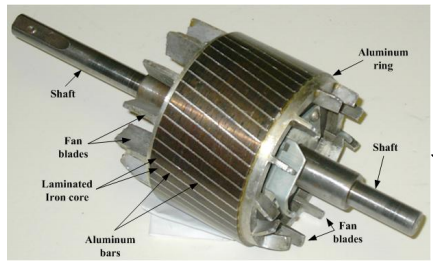
Squirrel cage rotor
It consists of a cylindrical core with slots nearly parallel to the shaft axis or skewed. Each slot contains an uninsulated bar conductor of aluminum. At each end of the rotor the bar conductors are short circuited by heavy end rings.
Advantages of skewing of cage rotor conductors
- Uniform torque is produced and the noise is reduced during operation.
- Locking tendency of the rotor is reduced.
- During locking the rotor and stator teeth attract each other due to magnetic action.
Slip rings
A rotor has a three phase winding similar to the stator winding. The winding terminals are connected to three slip Rings. The rings are mounted on the shaft with brushes resting on them. The brushes allow external resistors to be connected in series with the winding. The resistors are mainly used during startup under normal running conditions the windings short circuited externally.
Slip of Induction Motor
Motor never succeeds in catching up with the stator field. If it did so then there would be no relative speed between the two and hence no rotor emf no rotor current. So no torque to maintain rotation. For this reason rotor runs at a speed which is always less than the speed of the stator field. The change in speeds depends upon the load on the motor. The change between the synchronous speed Ns and the rotor speed N can be expressed as a %age of synchronous speed, known as the slip.
S= (Ns-N/Ns) ×100
Rotor voltage and current Frequency
The rotor winding frequency is variable and depends on the change between the synchronous speed and the rotor speed and the rotor frequency depends upon the slip.
Stator circuit model
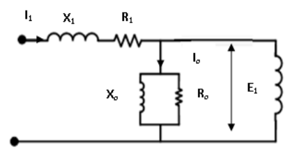
The induction motor stator model is
The self-inductance in stator windings which must be represented in equivalent circuit of machine. The Stator resistance called R1 and stator leakage reactance called X1. They appear right at input to machine model. The copper losses in an induction motor can be represented by a shunt resistance because stator and rotor are magnetically coupled a magnetic reactance just as in a transformer, shunted to the shunt resistance.
The magnetizing current I is considerably larger in the case of the induction motor as compared to a transformer. The reactance Xo in an induction motor will have a much smaller value. Io is about 2 to 5% of the rated current but in an induction motor it is approximately 25 to 40% of the rated current depending upon the size of motor.
The principal of operation:-
There are two methods for Single phase induction motor operation
- Double revolving field theory
- Cross-field theory.
Double revolving theory is the easier of the two methods
Double revolving field theory
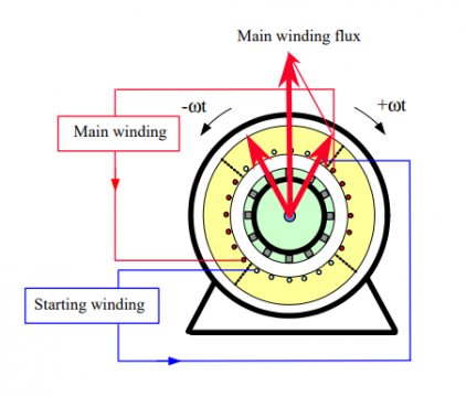
- Single phase ac current supplies the winding that produces a pulsating magnetic field.
- Pulsating field can be divided into two fields which are rotating in opposite directions.
- Interaction b/w the fields and the current induced in the rotor bars generates opposing torque
- Interaction between the fields and the current induced in the rotor bars generates opposing torque
- Only the main field energized the motor will not start
- External torque moves the motor in any direction the motor will begin to rotate.
- The Rotating fields produces a voltage in the rotor which drives current and produces torque.
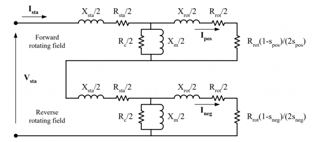
- The Equivalent circuit is similar to the equivalent circuit of a three phase motor, can represent each field
- The Parameters of the two circuits are the same with the exception of the slip.
Input power:
S = V I
Developed or output power
Initial torque
Single phase motor initial torque is zero because of pulsating s magnetic flux. Starting of the motor need the generation of a rotating magnetic flux similar to the rotating flux in a three-phase motor. Perpendicular Windings that have currents 90° out of-phase can generate the necessary rotating magnetic fields which start the motor. And the Single phase induction motors are built with 2 perpendicular windings. The phase shift is achieved by connecting
- Resistance in series with the starting winding.
- Inductance in series with the starting winding.
- Capacitance in series with the starting winding.
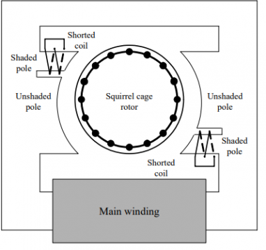
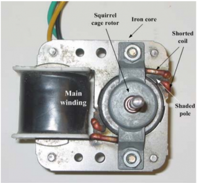
Frequently used is a capacitor to generate the initial torque. Less effective but more economical method using shaded pole motors Motor has two salient poles excited by ac current. Pole includes a small side that has a short circuited winding. This section of the pole of motor is called the shaded pole.
Major winding generate a pulsating flux that links with the squirrel cage rotor.
Produced flux induces a voltage in the shorted winding. The Induced voltage generate a current in the shorted winding. And the Current produces a flux that opposes main flux in the shaded pole. And result is that the flux in the unshaded and shaded portion of the pole will be unequal. The amplitude and the phase angle both will be different.
Two fluxes produces an unbalanced rotating field. Field amplitude changes as it rotates. This rotating field produces a torque which begin the motor in the direction of the shaded pole. Initially torque is small but sufficient for fans and other household equipment requiring small starting torque. Motor efficiency is poor but it is cheap. Motor has two salient poles excited by ac current and each pole includes a small section that has a short circuited winding.
Types of Single phase Induction Motors
Single-phase motors are as
- Split Phase Induction Motor
- Shaded Pole Induction Motor
- Permanent Capacitor Induction Motor
- Capacitor Start Induction Motor
- Capacitor Start Capacitor Run Induction Motor
Split Phase Induction Motor
The type of motor with an extra winding is wounded on the same core of the stator. There are two windings in the stator. The First winding is known as the main winding and 2nd winding is known as starting winding or auxiliary winding. Centrifugal switch is connected in series with the extra winding.
Auxiliary winding is highly resistive winding and main winding is highly inductive winding. Auxiliary winding has few turns with a small diameter.
Purpose of auxiliary winding is to make a p.d between both fluxes produced by the main winding and rotor winding. The Current flow through the main winding is IM and the current flowing through the auxiliary winding is IA. Windings are parallel and supplied by voltage V. Auxiliary winding is highly resistive in nature. Main winding is highly inductive in nature. And current IM lags behind the supply voltage with a large angle. Total stator flux is induced by the resultant current of these two winding. This will create a phase difference between fluxes and resultant flux produces a rotating magnetic field. And the motor starts rotating. Winding only uses to start the motor. Winding is not useful in running condition. When the induction motor reaches 75 to 80 % of synchronous speed the centrifugal switch opens. Hence auxiliary winding is out from the circuit. Motor runs on only main winding.
Phase difference generated by this method is very small. Hence the initial torque of this motor is poor. This Motor is used in low starting torque uses like a fan, blower, grinder, pumps, etc.
Shaded Pole Induction Motor
This induction motor has a different construction and working principle. The type of motor does not require auxiliary winding.
The motor has stator projecting pole and rotor is the similar as squirrel cage induction motor. The stator poles are constructed specially to create a rotating magnetic field. Pole of this motor is divided into 2 parts shaded part and un-shaded part. It can also be created by cutting pole into unequal distances.
Copper ring is placed between small parts of the pole. Ring is a highly inductive ring and it is known as a shaded ring or shaded band. Part at which shaded ring is paced is known as shaded part of the pole and the remaining part is an unshaded part.
An alternating supply passing through the stator winding the alternating flux induced in the stator coil. Because of flux a little amount of flux will link with shaded ring and the current will flow through a shaded ring.
Lenz law says the current passing through coil is opposite in nature and the flux produced due to this coil will oppose the main flux.
Shaded ring is a highly inductive coil. Hence it will oppose the main flux when both fluxes are in the similar direction and will increase the major flux when both fluxes are in the opposite direction.
It will create a phase difference between the main flux (stator flux) and rotor flux. Due to this a phase difference is very less. Hence the starting torque is very less. Motor is used in like toy motor, fan, blower, record player, etc.
Capacitor Start Induction Motor
An advanced version of the Split phase induction motor and disadvantage of split-phase induction is low torque production. Because the phase difference created is very less.
The disadvantage become less in this motor with the help of a capacitor connected in series with auxiliary winding.
Capacitor Start Capacitor Run Induction Motor
In this motor two capacitors are connected in parallel with series in auxiliary winding. Two capacitors are used out of one capacitor is used only for starting (starting capacitor) and another capacitor is connected permanently with the motor and initial capacitor has high capacitance value and the running capacitor has low capacitance value. Initial capacitor is connected in series with a centrifugal switch that will open at the speed of the motor is 70% of synchronous speed.
Starting condition both running winding and auxiliary winding connected with motor. The starting torque and efficiency of this motor are very high. This can be used in high initial torque is required like a refrigerator, air conditioner, ceiling fan, compressor, etc.
Permanent Capacitor Induction Motor
The Low rating capacitor is connected constantly with the auxiliary winding. And this capacitor has low capacitance. This capacitor is used to increase the initial torque but it is less as compared to the capacitor start induction motor.
Power factor and efficiency of motor are effectively high and it has a high starting torque that is 80% of full load torque.
Motor is used in an exhaust fan, blower, heater, etc.
Single Phase Induction Motor Applications
Single phase induction motors are not self-running and less efficient than three phase induction motor
- Clocks
- Refrigerators
- freezers
- heaters
- Ceiling fan, exhaust fans, air coolers and water coolers.
- Blowers
- Washing machines
- machine tools
- Dryers
- Type writers, Photostats and printers
- Water pumps and submersible
- Computers
- Grinders
- Machines for drilling
- Home instrument, equipment and devices etc.
Induction Motors Advantages & Disadvantages
Advantages of Induction Motors
- Construction of a motor is very simple and robust.
- Working of an induction motor is very simple.
- Operate in any environmental condition.
- Efficiency of the motor is very high.
- Maintenance of an induction motor is less compared to other motors.
- Single excited motor. Hence, it needs only one supply of source. It does not require external DC supply for excitation like a synchronous motor.
- Induction motor is a self-starting motor. So, it does not require any extra auxiliaries for the starting purpose for normal operation.
- Cost of this motor is very less compared to other motors.
- Life span of this motor is very high.
- Armature reaction is less.
Disadvantages of Induction Motors
- Power factor is very less. and it draws more current due to which copper loss is more which reduce the efficiency during light load condition
- Starting torque of this motor (squirrel cage induction motor) is not less.
- Induction motor is a constant speed motor. Application where variable speed requires, this motor is not used.
- Difficult Speed control of this motor.
- It high starting inrush current which causes a reduction in voltage at the time of starting.



I’m very grateful to you for the post like this. You cleared all my doubts about induction motor especially the “Squirrel cage rotor” section.Very Informative post.
Great post keep it up
find stylish name font Stylish Name Font