STM32 Blue Pill Arduino IDE Getting Started Tutorial, STM32 Boards
Table of Contents
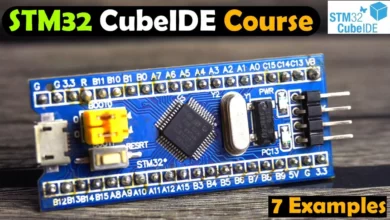
STM32 Blue pill board:
The blue pill which is also known as the stm32f103c8t6 this is by far the most popular one that shows up when I am searching for starter stm32 boards and honestly I think it is just because it has a nickname blue pill. Unlike Arduino, stm32 doesn’t really have a whole lot of nicknames they’re almost always referred to by the part number themselves. The part number tells us a lot about the chip. I think the most important parts are these first few digits here the f-103 and everything after that is kind of more of the technicalities like how many pins there are or what the footprint looks like. So it is pretty common to see people reference shorter part numbers to abbreviate or generalize them.
The blue pill rocks cortex m3 architecture more on that later it is a very minimalist design meaning there’s just the microcontroller and not much else on this board. It has Arduino support meaning that you can program this using the Arduino IDE, if you really want and these things are incredibly cheap you can get them for about two to four dollars and after working with Arduino for a long time the specs on this blew me away.
| Blue Pill | Arduino UNO | |
| Clock speed | 72 MHz | 16 MHz |
| Program Memory | 128 KB | 32 KB |
| RAM | 20 KB | 2 KB |
| Serial | 3 | 1 |
| I2C | 2 | 1 |
| SPI | 2 | 1 |
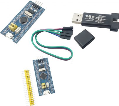
It is pretty much better or faster in every category. So if you are already comfortable with the Arduino IDE and programming language and you really just want a performance boost you can pick one of these up and get started pretty easily. The chip comes with a pre-installed boot loader to make it really easy to hook up over USB and program it for your first time through the Arduino IDE. However, I wanted to be able to buy a blank chip and put it on my own custom circuit board, so, I wanted to know what it would take to program this without the built-in boot loader. So to program this without using the boot loader that’s built-in, you’re going to need a programmer such as the st-link v2. If you’re coming from a background in Arduino programmers might be new to you. The only thing that you need to know about a programmer is it’s a special piece of electronics that’s able to erase and reprogram the microcontroller. You have probably heard the word bootloader thrown around here and there and that is really just code that lives on the microcontroller and it allows you to reprogram itself using some other methods. So, you could plug in a USB cable or a serial cable and transmit data and the chip would reprogram itself. It is not uncommon for a dev board to come with a bootloader pre-installed.
Amazon Purchase Links
Other Tools and Components:
Super Starter kit for Beginners
PCB small portable drill machines
*Please Note: These are affiliate links. I may make a commission if you buy the components through these links. I would appreciate your support in this way!
STM32 Blue Pill starting with Arduino core:
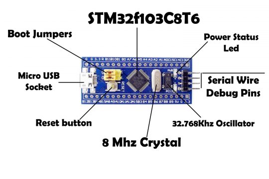
Now we will implement Arduino core onto stm32 blue pill module. This stm32 blue pill module is built on arm cortex-m3 STM32f103C8T6 microcontroller. This is got USB, micro USB socket to good jumpers and 8 megahertz crystal and then 32.768Khz crystal oscillator and serial wire debug pins. This microcontroller has the capacity of flash 128KB and the RAM 20KB clock speed up to 72 megabytes.
STM32f103C8T6 Pinout:
By two methods we can upload Arduino code onto stm32 blue pill.
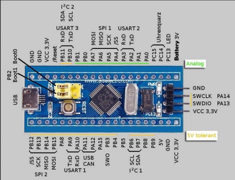
One is through UART. There are a total of 3 UART ports. UART1 is available on pins PA9 and PA10. UART2 is available on pins PA2 and PA3. UART3 is available on PB11 and PB10, these two pins are also used as the I2C 2 bus, so PB10 is SCL and PB11 is the SDA. So, out of these three UART ports we will be using only the UART1 port. UART1 is capable of uploading through serial for this you need a USB to TTL module.
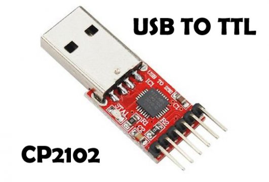
I am using here a USB to TTL module built on CP2102, USB upload is also possible.
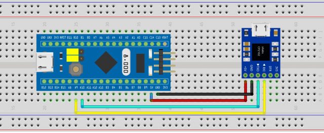
At the top you will see 4 pins which are the debug pins labelled as GND, SWCLK, SWDIO, and VCC 3.3V. These are the interface headers through which you can also upload code, for this you need st-link debugger. The stm32 blue pill is breadboard friendly you can easily plug it onto your breadboard and the connection to USB to TTL is simple. Only 4 wires are required.
You can use the 5 volt pin and connect it to 5 volt of USB to TTL and ground to ground. The 6th pin from the top is the PA9 which is TxD this goes to RxD of USB to TTL and the 7th pin is PA10 that is our RxD pin which goes to TxD of USB to TTL. No separate power source is required when you plug on the USB to PC. It will supply the voltage you can see the yellow line in the stm32 pinout image these all pins are 5 volt tolerant. So you can safely use this USB to TTL device.
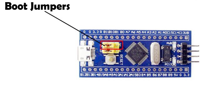
After you have connected your USB to TTL converter with the STM32. You will need to do one more change. You can see these Yellow colour Boot Jumpers, you will need to change the position of the jumper marked with Red colour. So simply unplug this and connect it again but this time the right leg and the middle leg should short. So, at this point, now you are all set. Now you can connect your USB to TTL converter with the computer or laptop through a cable and the LED will light up.
How to connect STM32 Blue Pill with Arduino IDE?
Once the STM32 board is turned ON, now press the reset switch. The device is ready for use, Make sure you have installed the CP2102 driver otherwise the USB to TTL will not work. If you have already installed the CP2102 then you can check the port allotted to the USB to TTL device. You will see a communication port number, this will be your com port and you will need to select this while uploading the code.
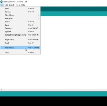
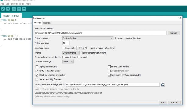
To install the Arduino core open the Arduino IDE and under file preferences at
The bottom you paste the paste this link.
http://dan.drown.org/stm32duino/package_STM32duino_index.json
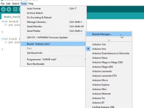
Now under tools board > boards manager.
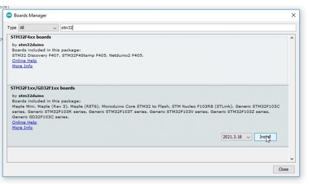
You search for stm32f1 for this you need internet connection search for stm32f1 and then select the STM32duino and select the latest version to install it.
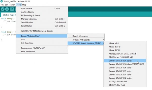
It will take some time to install. When you are done with the installation; close your Arduino IDE and reopen it and under tools boards you can see the various stm32 devices. Select the board as stm32f103c series and variant as “STM32F103C8 (20k RAM, 64K Flash)”
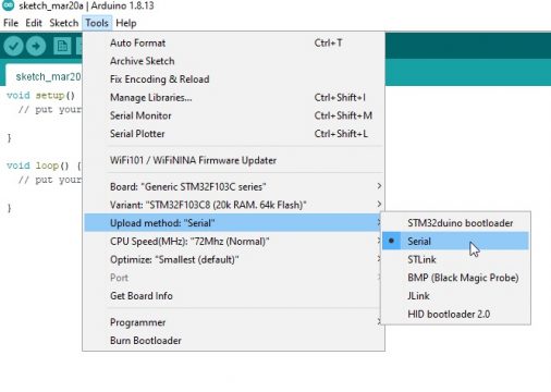
CPU speed is default 72 megahertz and upload method you should select as serial. This is very important, different methods of upload is possible you select serial. You can see a serial st-link bootloader out of this you select serial.
So, we are done with all the settings, and now we need to run a program. We have the LED blink example code which comes with the Arduino IDE. Or you can simply copy and paste the following code. On STM32 board the Built-in LED is connected with the PC13 you can check this in the STM32 Pinout diagram given above.
STM32 LED Blink Program:
|
1 2 3 4 5 6 7 8 9 10 11 12 13 14 |
#define LED_BUILTIN PC13 // STM32 built-in LED is connected with PC13 // the setup function runs once when you press reset or power the board void setup() { // initialize digital pin LED_BUILTIN as an output. pinMode(LED_BUILTIN, OUTPUT); } // the loop function runs over and over again forever void loop() { digitalWrite(LED_BUILTIN, HIGH); // turn the LED on (HIGH is the voltage level) delay(1000); // wait for a second digitalWrite(LED_BUILTIN, LOW); // turn the LED off by making the voltage LOW delay(1000); // wait for a second } |
Once the program has been uploaded now you can disconnect your STM32 board, and again shift the boot jumper back to its original position for the normal operation. If you will need to upload another code, again you will need to change the position of the jumper. It’s quite simple and doesn’t take much time. So, anyhow, when you turn on the STM32 the LED will start blinking. It will continue to turn ON and turn OFF at a 1 second interval as defined in the code. Currently I am using 1 second delay as 1000milliseconds = 1 second.
STM32 boards:
STM32 Discovery boards:
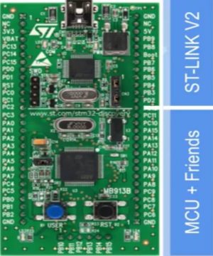
For this series next up we have the stm32 discovery boards now unlike the blue pill this is not a specific board. This is more of a family of boards the purpose of the discovery boards is to kind of give you all of the tools that you need in order to get started with a new chip. This specific board is the f-100 which is awfully similar to the f-103 which is what we saw with the blue pill. So this discovery board and the blue pill itself are pretty similar. One thing that the discovery boards have that the blue pill does not is a built-in st-link v2 programmer that means that you don’t need one of these to program it even if the chip was blank. They even draw a little line over here to show you where the st-link v2 stops and then the actual microcontroller stuff starts.
There are tons of different variants of the discovery boards but pretty much all of them come with a built-in programmer. Some user programmable buttons and leds and some of the fancier boards give you fun things to play with like microphones or accelerometers.
STM32 Nucleo boards:
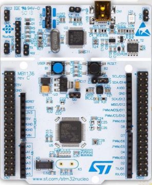
The next up we have the nucleo series which is another family of boards just like the discovery there are a few different variants of the nucleo boards like the nucleo 64, the 144 and the 32 and I am fairly certain that the only difference between these are the form factors. The only ones I have used are two of the nucleo 64 series boards that are both slightly different. One of the interesting things about the nucleo 64 is that it has the Arduino pin out on it. The pins seem to line up in a way that would make it Arduino compatible this would be useful for things like shields or hats that are compatible with the Arduino. Just like the discovery they put in a built-in programmer on the top this time they really drew a lot of attention to making sure that you realize that the st-link v2 is separate from the main microcontroller because. They added the ability to snap it in half to separate the two. It has been really tempting to snap this off. Just like the discovery boards there’s also a user programmable button over here and also an led somewhere in this area these boards tend to be about 10 to 25 dollars a piece.
STM32 Eval Boards:
The last thing on my list is the eval or evaluation boards these things are incredibly over. They are designed to showcase as many of the features as possible so they add all of the bells and whistles that you could possibly want so for example if the chip can drive hdmi. You can expect there to be an HDMI port on here these things pack a massive punch but that being said they cost around 200 to 600 each out of everything that I listed today this is probably the only one that i would not recommend to get started with stm32. This is more geared towards people that are really trying to make the most out of their stm32.
How to read STM32 part number:
If we look at the microcontroller’s part number we can see this letter that comes directly after stm3 this tells us what type of microcontroller it is:
- F is used for the foundation and sometimes high performance
- G represents mainstream
- L is low power
- h is high performance and
- w which is for wireless
The number that comes directly after the type is the core this number represents what type of cortex this microcontroller is using if you’re curious this is what they represent but it’s not terribly important.

Do you have some tut for programming a bootloader to a barebone STM chip?