Triode, Construction, Operation, Parameters, solved examples, uses, as Amplifier
Last Updated on March 5, 2022 by Engr. Shahzada Fahad
Table of Contents
Triode, Description:
Triode, Construction, Operation, Parameters, solved examples, uses, and Triode as Amplifier– In 1907, Lee De Forest added another element control grid, to diodes’ existing two elements- cathode and anode, as a result of which triode valve or tube came into existence. This has the capacity to amplify weak radio signals. Radio communication, broadcasting and common electronics witnessed a great development and benefits through this invention.
Triode Construction
As is evident from the name, triode tube is composed of three electrodes (Tri means three while Ode means electrodes). One of these is called cathode (filament type or indirectly heated oxide coated type), second one anode (plate) and the third one control grid. Grid is kept between cathode and anode and it is closer to cathode as compared to anode. In other words, triode valve is similar to diode with the exception that there is a grid between cathode and anode. The construction of triode and its symbols have been presented in the figure 1.9
In this tube, control grid is composed of a fine wire mesh structure or circular helix (though grid’s structure may be in other shapes as well apart from circular helix e.g. smooth, oval, spring type or stairs like). The objective of making grid as a mesh wired tube is to allow electrons pass through it freely. Due to its mesh structure, grid does not pose any direct hurdle in the way of flow of electrons moving towards anode, however it has striking influence on the electric field created between anode and cathode, when voltage is supplied to the grid, as result, the total flow of electrons gets influenced.
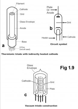
Wires of different sizes are used in control grid according to designs and the electric field formed inside the tubes. Grids are usually made from Microbe, molibanium, nickel, iron, tungsten, tantalum and different alloys. The size of triodes valves depend on its power rating and purpose of its usage. They are available in different sizes due to the empty space available between its electrodes. It is to be remembered that that plate current depends on construction of grid and its spacing.
Triode Control Grid Action or Operation
As grid is closer to cathode, therefore, grid potential plays an important role in controlling the flow of electrons within a tube, i.e. it regulates the flow of electrons inside the grid circuit, as a result plate/ anode current is controlled. In other words, when voltage is supplied to grid, there is a great influence of grid voltage on electric field and anode current as compared to uniform supply of voltage to anode. In this way, grid has a controlling effect on anode current.
Three different operating voltages are required for each electrode of triodes, so that each of the electrodes could be made functional in a correct way. Anode is normally connected to a high positive voltage, so that it could attract electrons emitted through cathodes. Filament or heater is connected through relatively low AC/DC voltage, so that they could emit electrons from cathode after reaching a particular emitting temperature. At end, voltage is supplied at grid to control the flow of anode current. These voltages are usually of 2 types. One of it is fixed direct voltage, which is also called biased voltage. There are normally few negative volts relative to cathode, the function of which is to operate/ bypass tube with its specific characteristic’s curves, at specific points, so that a specific quantity of anode current always keep flowing inside the tube. Other voltages provided to the tube are variable positive voltages which are also called signal voltages. The objective of these voltages is to convert current passing through tube according to variation signals in the tube, so that anode current could be amplified according to signal voltages. A small change of signal voltage at grid, leads to a significant variation in anode current, which is called amplification.
In figure 1.10, the process of a grid in a triode has been explained through simple pictures. Instead of supplying bias or a signal voltage to grid, the value of bias voltage has only been changed in every part of the pictures. DC supply voltages (which are obtained through batteries), have been measured with respect to the cathode. Whereas, anode’s current value has been measured by fixing a mille ampere meter in anode and cathode circuits.
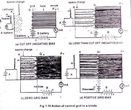
In figure (a) cathodes’, grid’s and anode’s cross section has been displayed in a simple way. Heater is provided voltage through battery A, while cathode has been emitting electrons in a normal quantity. Anode has been supplied high positive voltage and if grid is not provided enough negative voltage from battery C, anode will attract too many electrons towards it through the space charge the method of control grid has been explained below.
Cut-off Box
When the control grid of a triode tube is made too negative in relation to cathode, the flow of electrons from cathode to anodes halts completely and anode/ plates current become zero. The value of grid voltage, on which plate current become totally negative, is called cut-off grid voltage or cut-off bias. It is to be remembered that at cut off grid voltage, repelling power of grid and anode attraction are mutually equal and electrons emitted from cathode assemble in the form of cathode’s space charge instead of going towards anode through grid.
The value of cut-off grid voltage depends on anode voltage and characteristics of tube. The cut-off grid’s value turns more negative with an increase in the value of anode voltage.
When grid is provided large negative voltage, the electrostatic field found normally between anode and cathode, cannot enter cathode and it finishes up on grid wires, as is obvious from the lines of force spread between the grid and anode. (Figure “a”). In such a situation, grid completely neutralizes electrostatic field and anode’s attraction. Therefore, no electrostatic field exists near cathode for carrying electrons emitted from cathode, to anode, due to which field current is zero. This has been displayed through zero reading on mile ampere meter in figure (a).Thus, a great deal of space charge gets collected between cathode and grid. Minimum negative voltage between cathode and grid at which anode current stops or cuts-off is called cut-off bias. Increasing bias voltage, in proportion to cut-off value, has no effect on the function of tube.
Less than Cut-off Bias
If the value of negative bias voltage supplied on grid is lowered a little in proportion to cut-off bias, the field existing between anode, cathode and grid cannot fully be neutralized and some lines of force enter cathode through the grid wires. As a result, some of the electrons move towards positive anode from space charge through the grid wires, as depicted by an ampere meter (mA) in the figure (b). As the grid voltage is lowered further (that’s grid becomes less negative) more and more electron passes to anode through the grid wires and anode current also increases consistently in a same ratio. However, it has to be remembered that so long as negative bias voltage remains on grid with respect to cathode, grid does not attract electrons to it.
Zero Grid Bias
When grid voltage is zero (or battery is removed from C circuit) positive voltage supplied on anode generates a strong electric field on cathode and anode attracts a large number of electrons towards it, through the grid wires (or a large number of electrons move towards anode through the grid lines), due to which there is a substantial increase in the value of anode current (as explained in figure (c). As grid has to be on a zero voltage with respect to cathode, it therefore, do not attracts electrons itself.
Positive Grid Bias
When grid is turned positive with respect to cathode, (or if the polarity of grid battery or battery C is reversed, as shown in figure (d), grid becomes positive with respect to cathode). Grid potential in support with anode voltage generates a very strong electrostatic field on cathode, due to which anode current passes through the tube in a profuse quantity. In other words, when grid is turned positive with relation to cathode, it neutralizes space charge in the cathode’s region, due to which too much current passes through anode. If grid is turned positive step by step with regard to cathode, a point comes when electrons emitted from cathode move to anode at a very brisk speed (i.e. the speed at which electrons emit from cathode, anode attracts them immediately at the same speed). In such a situation, space charge cannot develop at all and anode current reaches its saturation value. Remember that further addition in grid or anode voltage has no bearing on the value of anode current.
Fig (d) explains that some lines of force of electric field come to an end due to a positive grid voltage, due to which some electrons move towards positive grid by way of attraction. Thus, current starts flowing between grid and cathode (through battery C). In this case, power consumption starts in grid circuit. In order to avoid this consumption of power and avert too much saturation of current, valves are normally operated on negative grid voltages compared to cathode (so that tube could be protected from a potential damage) i.e. tubes are normally supplied negative grid voltages.
Amplification
When desired voltage is provided to all the electrodes of a triode valve, cathode emits electron while anode attracts these electrons towards it, due to which current passes through the valve circuit. In such a situation, if a slight change is made in grid voltage (say 1 volt), a major change results in anode voltage. This method is called amplification. This function of grid inside an electron tube makes an amplifier.
We know that anode current can be determined in triode through electro static field, which sets up due to a mutual process of grid and anode on the space charge located near the cathode. As grid is closer to space charge compared to anode, grid voltage therefore, has a greater impact on anode current than an anode voltage. Thus, if grid voltage becomes too negative, anode current also get less and likewise anode voltage will also diminish. If a load resist is inserted in the series anode’s circuits, the voltage drop parallel to this resister depends on anode current. Anode current is, thus controlled through grid voltage (remember that grid is controlled through such controlling property). Thus, a significant change occurs in anode current and the resulting voltage parallel to load resistance, due to a minor change in grid voltage (grid signal). In other words, signal voltages supplied on grid amplify an anode value circuit and this amplification in grid circuits occurs without consumption of power.
Triode Characteristics Curves
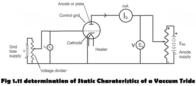
The curves which reflects relationship among anode voltage, grid voltage and anode current in a triode, are called triode characteristics curves. We know that anode or plate current in a triode depends on anode /plate voltage and grid voltage, provided cathode’s temperature remains constant. Cathode temperature is always kept constant as filament has to be provided a particular voltage. In other words, if anode voltage (Vp or Eb) is kept constant while the grid voltage keeps fluctuating, a proportionate change occurs in the plate current accordingly. Similarly, if anode or plate voltage while grid’s voltage is remains constant, even then change occurs in plate current (that change occurs in plate current in two ways) The curves, which reflect variation in anode current resulting from keeping the anode voltage constant and changing grid voltage or keeping grid voltage constant and changing anode voltage, are called triode characteristics curves. Such static characteristics curves can be understood through a circuit shown in figure 1.11. (Term static shows that these characteristics can be achieved when cathode is provided with different DC voltages without any related circuit. Whereas by dynamic characteristics, we mean those characteristics which are acquired under operating condition through fixing a resist in anode circuit for the supply of signal voltage and getting power through valve.
There are, thus three types of triode characteristics curves
- Anode or Plate Characteristics
These characteristics curves are also known as anode current- anode voltage characteristics (Ip– Ep)
- Mutual or Transfer Characteristics
Also known as anode current- grid voltage characteristics (Ip-Eg)
- Constant Plate Current or Amplification Characteristics
Also called anode voltage- grid voltage characteristics
Anode or Plate Characteristics
These curves are drawn between different values of anode current and anode voltage, while grid voltage is kept constant. Thus, if the grid voltage is retained constant, whereas anode or plate voltage keeps on changing, different anode currents are received on different anode voltage values. These curves, which come into effect due to mutual relationship between different quantity of anode current and anode voltage, are called anode or plate characteristics curves. It has to be remembered that the value of plate current depends on the value of plate voltage. Curves made between anode current and anode voltage, keeping grid voltage constant, are not absolutely straight, and are rather parallel to each other with similar shapes. The lower part of such curves is a bit curved/ tilted, whereas the upper or middle are is almost linear. (Figure 1.12 a). Remember that maximum value of a grid voltage (Ec or Vg or Eg) is kept zero while drawing these curves and all the curves are drawn on negative grid voltage. New curves are drawn only when grid voltage is connected to some other fixed value.
Mutual or Transfer Characteristics
If anode /plate voltage is kept constant while the grid’s voltage is changed, a change results in anode or plate’s current. The curves which depict relationship between different values of grid voltage and anode current, keeping the anode voltage constant, are called grid, mutual or transfer characteristics curves of a triode. These curves generated on different anode voltages, are explained in figure (b). These curves are also tilted or curved a bit on the bottom, while parallel or linear from above. Triode always operates in the linear part of the curves, because plate current does not increase with the same ratio as result of an increase in grid voltage on curved portion of the characteristics curves.
It is visible in the figure that grid voltages get lowered on specific anode voltages, due to which anode/ plate current also get lesser ultimately becomes zero (This is cut-off bias). Negative grid voltage keeps moving in negative direction with an increase in anode voltage value, resultantly anode current becomes zero.

Constant Plate Current or Amplification Characteristics
The curves drawn between plate voltage and grid voltage through keeping anode or plate current constant are called amplification curves or constant plate curves. Constant plate curves of a triode have been shown in figure 1.12 (c)
At the time of drawing these curves, first a high voltage is exerted on anode. Then heat level of maximum anode current is acquired through adjustment in the grid voltage, at which characteristics are found. Anode voltage is lowered step by step and on every step, grid voltage is re-adjusted, so that the same anode current could be obtained. Different curves are made through repeating this process with different anode currents.
Remember that afore mentioned curves impart similar information. Through information of one set, curves of other characteristics can also be prepared. Through such characteristic’s curves, we come to know about places or destinations, on which no distortion occurs through the application of triode.
Triode Parameters or Coefficients
Important ratios which are acquired via triode characteristics curves, in order to judge its performance are called triode parameters or triode coefficients.
There are three types of tube parameters mentioned as follows:
- Amplification Factor
- Plate Resistance
- Trans Conductance or Mutual Conductance
Amplification Factor
The ratio of change between plate voltage and grid voltage is called amplification factor, provided plate current (Ip or Ib) remains constant. Amplification factor is denoted by Greek letter µ.
µ = ∆Vp/∆VG or ∆Eb / ∆Ec= Small change in plate voltage/ Small change in grid voltage … (Ip or Ib remaining constant)
Remember that the value of µvaries between 15-100 in a triode. Due to a certain ratio between the two values, there is no unit of amplification factor and it mainly depends on the structure of tube. Amplification factor is normally a slope of constant plate current’s characteristics (the ratio of a small change in anode or plate voltage to a small change in grid voltage, anode current being kept constant, is called amplification factor)
Plate Resistance
It refers to the internal resistance or opposition of a tube in the way of flow of electrons from cathode to anode, which can be found between anode and cathode at the time of conversion of anode current. Plate resistance is defined as a ratio of change in plate voltage to the ratio of change in plate current, grid resistance remaining constant. It is denoted by rp and its measurement is done in KΩ. Mathematically,
Rp = Change in plate voltage/ change plate current = ∆Vp /∆Ip (With Vg constant)
The value of plate resistance shows how plate voltage effects plate current, with a constant grid voltage. Normally, it remains between 8KΩ – 40KΩ. Plate resistance coefficient can also be determined through reciprocal of plate characteristics curves’ slope.
Trans Conductance or Mutual Conductance:
The ratio of a change in plate current relative to change in grid voltage is called mutual conductance, provided plate voltage does not change. It is denoted by gm and measured in µΩ.
gm= small change in plate current/ small change in grid voltage= ∆Ip/ ∆V0(With Vp being constant)
Trans Conductance is the most important co-efficient amongst all of the three constants, as it depicts control grid’s capabilities or effectiveness for generating protected changes in plate current (or in tube’s output signal). Its value can easily be obtained through the slope of mutual characteristics. Normally, its value varies between 1000 µΩ to10000 µΩ. However, it has to be remembered that variations in plate current and grid voltage should be minimum in order to obtain an authentic value.
Relation between µ, rp and gm
According to their definitions, all three valves are closely inter-related and this relationship can easily be reflected through multiplying definitions of plate resistance and trans-conductance i.e.
rp x gm =∆Vp/∆Ip x ∆Ip/∆Vg= ∆Vp/(∆Vg )= µ
Remember that mutual co-ordination among these three parameters can also be shown via dividing amplification factor definition by definition (formula) of anode resistance i.e.
µ/rp = (∆Vp/∆Vg)/(∆Vp/∆Ip)= (∆Vp x ∆Ip)/(∆Vp x ∆Vg)= ∆Ip/∆Vg = gm
Hence gm = µ/rp and µ = gm x rp and rp = µ/gm
If any of the two coefficients of valve are known, the value of the third can be obtained by using the above formula or relations. For comparison of different valves of similar nature, mostly comparison of trans-conductance among such valves is performed i.e. trans-conductance is used as a merit or standard. Trans-conductance shows relation between a valves’ amplification factor and its anode resistance High amplification factor is necessary in order to output voltages from low input signals. Inversely, there is a greater flow of anode current through low anode resistance, which brings about large output. Thus, measurement of voltages and power amplification in a particular tube can be done through trans-conductance. Remember that multiplication factor of rp gm always remain constant.
Example 1
In order to reduce the anode current of a valve from 14.4 Ma to 8mA, the anode voltage is reduced from 125 volts to 100 volts, grid bias remaining constant. What is the anode AC resistance of the valve?
Solution:
Original anode voltage=125 V
Reduced anode voltage=100 V
Change in anode voltage=125-100= 25V
Original anode current=14.4mA
Reduced anode current=8mA
Change in anode current=14.4-8=6.4mA
Rp=∆Vp/ ∆Ip=25/6.4×10-3= 3906 ohms
Example 2
A reduction from 125 to 100 volts on the anode of a triode requires a change from 4 to 2.34 volts on the grid bias to maintain a constant flow of anode current. Through a valve, calculate the amplification factor.
Solution:
Change in anode or plate voltage ∆Vp/= 125-10=25V
Change in grid voltage ∆VG= 4-2.34=1.66V
Amplification factor µ=∆Vp/∆VG= 25/1.66=15 (Ans)
Example 3
A triode valve has a mutual conductance (gm) at 1.9mA/V and an amplification factor (µ) of 3500, what is the slop resistance of anode?
Given µ=3500, gm= 1.9×10⁻³ A/V
rp = µ/ gm =3500/1.9×10-3=1842000 ohms=1.84 MΩ
Example 4
What is the mutual conductance of a power triode having an anode resistance of1265 ohms and an amplification factor of 9.5
Solution:
Given µ =9.5, rp = 1265Ω
gm=µ/rp= 9.5/1265A/V=9.5×103/1265mA/V= 7.5mA
Applications or Uses of Triodes
Triodes tubes are normally used on audio and radio frequencies as an amplifier detector and oscillator. However, two defects are found in the usage of triode, the first defect being that its plate current partly depends on grid voltage and partially on plate voltage. The second defect being that when triode is used as an amplifier on a high frequency, its operation becomes unstable because of the existence of capacitance between grid and plate and oscillations produced in amplifier.
Triode as an Amplifier
We know that if control grid of a triode is turned too negative, the flow of electrons from cathode to anode either stops completely or it becomes too small. When grid voltage is kept less negative, i.e. less negative bias is provided to grid, the flow of electrons between cathode and anode increases. On the contrary, if grid is made positive with respect to cathode, anode current increases too much (the value of grid voltage, which makes it positive or negative in relation to cathode, is called positive or negative grid bias respectively). From this function of triode, it becomes clear that triodes’ anode current can easily be controlled through reducing or increasing grid voltage. Due to positive grid bias, a substantial increase in anode current or due to a steeply negative grid bias, the complete stoppage of anode current or its becoming zero, both these situations reflect extreme operations of diode. (The values of grid voltage, which makes it positive or negative in relation to cathode, are called positive and negative grid bias respectively). Thus, if triode is desired to be used as an amplifier, it is normally set in the middle part of the characteristic’s curves, so that no distortion is produced on its output. There is no direct benefit of the current passing through valve or tube; however, this change in current results a change in anode voltage, the initial change in grid voltage will amplify. Therefore, when triode is used as an amplifier, a load resistance is exerted on its plate (i.e. a resistor is set between anode and HT), which is called loader resistor and is depicted in figure 1.13. Thus, whenever there is a change in current passing through the resistor, the voltage drop also changes due to change in plate current paralleled to the resistor. This voltage change is greater with respect to the change in grid voltage, due to which a large change occurs on voltage being exerted on plate or anode (In other words, a change in resistor’s voltage effects a proportionate change in anode voltage or output). In this way, change in grid voltage having been amplified, reflects on plate/ anode as output voltage.
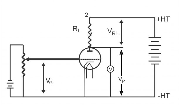
When a load resistance RLis inserted on triode circuit between HT and anode, HT voltage is depicted as under:
HT= VRL+Vp
When grid voltage becomes inordinately negative, anode current gets too low (as shown through figure 1.14 (a). There is an insignificant drop in voltage on the load resistor due to a decrease in anode current, thus a very little change results in anode voltage. Minor negative grid voltages have been shown in the figure (b). In this way, anode current gets increasing and voltage drop on load resistor also increases. i.e. a greater change occurs in anode voltage, due to which output voltage increases. As per figure (C), little or a very few negative voltages have been supplied to grid, due to which anode current gets quite large and voltage drop on the load resistor also intensifies. Consequently, a significant change occurs in anode voltage, therefore output voltage also witness an increase.

In this way, anode/ plate voltage can be increased manifolds due to variation in grid voltage. The ratio of change in anode voltage to a change in grid voltage is known as amplification or gain.
Above mentioned detail can be elaborated with the help of following example.
Suppose the quantities of a triode circuits are as under:
Grid voltage= -4 volt
Load resistor= 25 kilo ohm
HT on plate=225 volts
Anode or plate current= 4-milli ampere
Voltage drop on load due to this current= Rl x Ip=100 volt=25×103x4x10 -3
Therefore, anode voltage HT= Vp = HT Voltage- Load Resistor Drop (VRL) =225-100= 125 volts
If the grid voltage value is change from -4 volts to -2, anode current will increase to 5-milli amperes. Thus, voltage drop due to this current= 25×103x5x10-3=125volts
Therefore, anode voltage= 225-125=100 volt
Thus a 2 volt change in grid brings about 25 volts change in anode voltage. As such, the value of amplification or gain will be as below:
Amplification= small change in anode voltage/ small change in grid voltage= 25/2= 12.5
Limitations of a Triode:
We know that three electrodes at equal distances are found inside triode and any two of these electrodes assume the shape of a capacitor (According to fundamental electricity theory, metal plates function like a capacitor due to the existence of electro static field between any two charged metal plates. It has further to be remembered that several electrostatic fields exist amongst the charged electrodes of a triode and if a dielectric is put between these two charged metal plates or pieces, a capacitance occurs between these plates. Therefore, the following 3 capacitances are found in a triode, which are known as inter electrode capacitances (fig 1.15)
- Capacitance between grid and cathode (Cgk)
- Capacitance between grid and plate (Cgp)
- Capacitance between plate and cathode (Cpk)
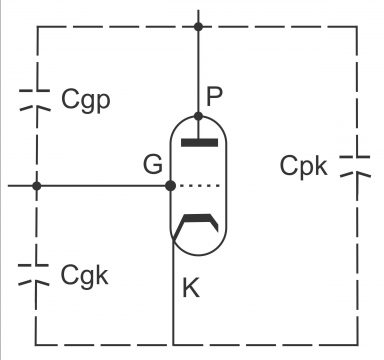
Inter electrode capacitance depend on the size of metal plates, distances between these plates and type of dielectric. However, the value of these capacitances is small (2-10micro-micro farads)
The value of capacitances on low frequency is small while the value of reactance is quite large (because XC=1/2 fc).However, if the number of radio frequencies is too high, reactance gets smaller. The unpleasant effects like oscillation and instability occur as a result of this. (In particular the mutual capacitance of a grid and anode (Cgp) has the capacity of an energy feedback from anode or output circuit to grid or input circuit, due to which unnecessary impacts take place). Therefore, it is not beneficial to use triode on so many frequencies. The inter electrodes capacitances in radar or similar other circuits, due to the use of ultra-high frequency (u.h.f) is highly objectionable. Therefore, in order to enhance the efficiency and improve characteristics of a triode, or for reducing inter electrodes capacitances of a triode, multi electrodes tubes are manufactured. For this end, a screen grid is included between a triodes control grid and its plate, due to which inter electrodes capacitances minimizes to a great extent. Screen grid is provided with a positive supply HT and its voltages are also less as compared to plate voltages.
Summary
- A triode is a tube consisting 3 electrodes consisting cathode (emitter), anode (collector) and a control grid (a fine wired-helix)
- The voltage supplied on the control grid is either fixed negative direct voltage, called bias or alternating voltage, called signals.
- Anode current in a triode is determined via mutual effects of electric field and control grid voltages generated by an anode. As control grid is closer to cathode as compared to anode, the effect of grid voltage on anode current is greater than the anode voltage. Thus, amplification of input signals becomes possible.
- When too much negative bias voltages are supplied on control grid, it neutralizes anode’s electro static field, due to which the flow of anode current stops i.e. anode current becomes zero. The minimum negative voltage at which the flow of anode’s current stops, is called cut-off bias.
- As soon as negative grid bias is minimized, grid cannot completely neutralize the electric field of a plate and anode current increases in proportion to a decrease in negative grid bias.
- When bias is made positive, grid’s field starts supporting anode. Through increase in the bias positive values, a point comes when anode current reaches its saturation value. This value is normally equal to the total supply of emitted electrons.
- The relationship emerging as a result of anode current, anode voltage and grid voltage is called triodes characteristics curves. When one of these variables is kept constant (at a different value for each curve), the relationship being developed between variables of other two, when depicted through curves on a graph paper, are known as triodes characteristics curves.
- When a steady DC voltage is supplied on electrodes, triodes static characteristics come into effect. Dynamic characteristics, develop under actual operating conditions of a triode (i.e. through supply of variable signal voltage on grid or through the induction of another resistance in anode circuit)
- Making equal changes in anode voltage or grid voltage on a straight (linear) part of the characteristics curves result in equal changes in anode current, which is essential for an undistorted amplification.
- Every triode value has important design factors (particulars or valve constants), amplification factors, AC anode resistance and mutual conductance or trans-conductance.
- Inter electrodes capacitances exist among cathode, anode and grid due to the presence of electronic field between these charged electrodes. These are denoted as Cgk, Cgp and Cpk.
- Grid to anode capacitance provides energy feedback from anode (output) circuit to grid (input) circuit, due to which oscillation occurs on radio frequencies.
For electronics and programming related projects visit my YouTube channel.
Previous article: diode, Construction, and Next article: Tetrode
Discover more from Electronic Clinic
Subscribe to get the latest posts sent to your email.


any student who wish to study semiconductor electronic devices should learn this article to visualise what goes on inside semiconductor diodes