Water Flow Sensor Arduino, Water Flow Rate & Volume Measurement
Last Updated on August 18, 2024 by Engr. Shahzada Fahad
Table of Contents
Description:
Water Flow Sensor Arduino, Water Flow Rate & Volume Measurement- In this Tutorial, you will learn how to accurately measure the Water Flow Rate and Water volume using the Water Flow Sensor YF-S401, Arduino UNO, and a 12v DC Water Pump.
Working on the Water Flow Sensor is a bit tricky whether you are using YF-S401 or YF-S201 Hall Effect Water Flow Sensor, and that’s the reason, most of the people complain about the wrong values. There are things that we need to take care of while using the Water Flow Sensor. As per the datasheet, when water flows through the rotor, rotor rolls. Its speed changes with different rate of flow. If we can keep the pressure and flow constant we can make an accurate water volume measurement system. I solved this problem by using a 12v Water Pump.
In this tutorial, I will also explain what’s inside a Water Flow Sensor and how it works. I will also explain the complete circuit diagram, making, and Arduino programming.
Without any further delay, let’s get started!!!
You can also ready my article on IoT based Water level monitoring and automatic water pump control system using the ESP32 WiFi + Bluetooth Module, Waterproof Ultrasonic Sensor, and the New Blynk V2.0 more…
Note: For the step by step explanation and practical demonstration watch video given at the end of this article.
Amazon Links:
Arduino Nano USB-C Type (Recommended)
*Disclosure: These are affiliate links. As an Amazon Associate I earn from qualifying purchases.
About the YF-S401 Water Flow Sensor:

This is the Water Flow Sensor which consists of a PVC body. This Water Flow Sensor is suitable to detect flow in water dispensers, water heaters, gardening or coffee machines.
Features:
Compact, Easy to Install
High Sealing Performance and this Water Flow Sensor has a High-Quality Hall Effect Sensor.
Specification:
Model: YF-S401
- Working Voltage: DC 4.5V
- Working Current: 15mA (DC 5V)
- Working Voltage: DC 5V~24V
- Water resistant 0.35MPa
- Flow Rate Range: .3~ 6L/min
- Load Capacity: ≤10mA (DC 5V)
- Operating Temperature: ≤ 80C
- Liquid Temperature: ≤120C
- Operating Humidity: 35% 90%RH
- Water Pressure: ≤ .8MPa
- Storage Temperature: -25 + 80C
- Storage Humidity: 25% 95%RH
- Internal diameter: 1.2mm;
- Error: +/-2L/min;
- Insulation resistance > 100M ohm
- Output pulse duty cycle 50% ± 10%
- Output pulse high level > DC 4.7V (input voltage DC 5V)
- Flow pulse characteristics F = (98 * Q) ± 2% Q = L / MIN
Download Water Flow Sensor Datasheet: yf-s401water flow sensor datasheet
As you can see in the picture above, this Sensor has a total of three wires, Red, Black, and Yellow. The Red wire will be connected with the Arduino’s 5 Volts, the Black wire will be connected with the ground and Yellow wire which is the signal wire will be connected with the Arduino’s pin number 2, which is the interrupt pin.
![]()
On the backside of this Water Flow Sensor, as you can see there is an arrow that shows the direction of the flow of water. So this side is the Inlet and this side is the Outlet.
Now let’s check what we have got inside this Sensor, and how this sensor actually works.

Inside this Water Flow Sensor, we have a high-quality Hall Effect Sensor. This sensor also has a rotor which rotates as the water flows from the inlet opening to the outlet opening. This rotor has a magnet which gives pulses to the Hall Effect Sensor. The flow of water or any other liquid should be in the direction of the Arrow.
The Water Flow Sensor for the Flow Rate and Volume Measurement using Arduino Uno, Mega or any other microcontroller board works on the principle of the Hall Effect.
Water Flow Sensor Calculation:
As you know,
1 Litre = 1000 mL
So, the range of this sensor is 300mL to 6000mL per minute.
At 1000mL you get 5880 pulses, but is that over a minute otherwise over a second its 5880/60 = 98 Hz square wave which has a period of 1/98 = 10.2 milliseconds.
For 1mL you calculate 5880/1000 = 5.88/60 = 0.098Hz with a period of 10.2 seconds. In the programming, I will be using the pulsein to measure the time of a pulse.
Water Flow Sensor Arduino Connection Diagram:
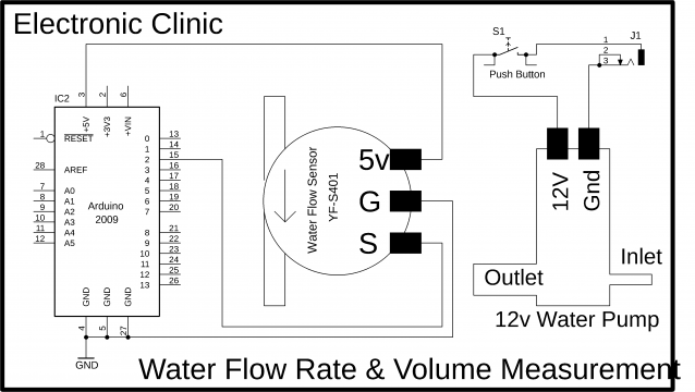
This schematic is designed in the Cadsoft eagle 9.1.0 version. If you want to learn how to make a schematic and PCB then watch my tutorial.
As you can see the connections are very simple. J1 is a female power jack and this is where we connect a 12v adaptor or battery. The 12 volts are used to run the 12v DC water Pump. The ground is directly connected with the Water Pump while the 12 volts are connected with the Water Pump through a Pushbutton.
The Water Flow Sensor 5v pin is connected with the Arduino’s 5 volts, the Ground pin of the Water Flow Sensor is connected with the Arduino’s ground and the signal wire is connected with the Arduino’s pin number 2 which is the interrupt pin. So for the pulses counting we will be using the Arduino’s Hardware Interrupt 0.
Making:

The complete making of the whole setup is explained in the video tutorial given at the end of this article. A pipe from the bottle is connected with the inlet valve of the 12v DC Water Pump and the outlet opening of the 12v DC Water Pump is connected with the inlet opening of the Water Flow Sensor. The 12v DC Water Pump is controlled using a Pushbutton. The three wires of the Water Flow Sensor YF-S401 will be connected with the Arduino. These three wires are connected as per the circuit diagram already explained.
Water Flow Sensor YF-S401 Arduino Programming:
|
1 2 3 4 5 6 7 8 9 10 11 12 13 14 15 16 17 18 19 20 21 22 23 24 25 26 27 28 29 30 31 32 33 34 35 36 37 38 39 40 41 42 43 44 45 46 47 48 49 50 51 52 53 54 55 56 57 58 59 60 61 62 63 64 65 66 67 68 69 70 71 72 73 74 75 76 77 78 79 80 81 82 83 84 85 86 87 88 89 90 91 92 93 94 95 |
int sensorInterrupt = 0; // interrupt 0 int sensorPin = 2; //Digital Pin 2 int solenoidValve = 5; // Digital pin 5 unsigned int SetPoint = 400; //400 milileter /*The hall-effect flow sensor outputs pulses per second per litre/minute of flow.*/ float calibrationFactor = 90; //You can change according to your datasheet volatile byte pulseCount =0; float flowRate = 0.0; unsigned int flowMilliLitres =0; unsigned long totalMilliLitres = 0; unsigned long oldTime = 0; void setup() { // Initialize a serial connection for reporting values to the host Serial.begin(9600); pinMode(solenoidValve , OUTPUT); digitalWrite(solenoidValve, HIGH); pinMode(sensorPin, INPUT); digitalWrite(sensorPin, HIGH); /*The Hall-effect sensor is connected to pin 2 which uses interrupt 0. Configured to trigger on a FALLING state change (transition from HIGH (state to LOW state)*/ attachInterrupt(sensorInterrupt, pulseCounter, FALLING); //you can use Rising or Falling } void loop() { if((millis() - oldTime) > 1000) // Only process counters once per second { // Disable the interrupt while calculating flow rate and sending the value to the host detachInterrupt(sensorInterrupt); // Because this loop may not complete in exactly 1 second intervals we calculate the number of milliseconds that have passed since the last execution and use that to scale the output. We also apply the calibrationFactor to scale the output based on the number of pulses per second per units of measure (litres/minute in this case) coming from the sensor. flowRate = ((1000.0 / (millis() - oldTime)) * pulseCount) / calibrationFactor; // Note the time this processing pass was executed. Note that because we've // disabled interrupts the millis() function won't actually be incrementing right // at this point, but it will still return the value it was set to just before // interrupts went away. oldTime = millis(); // Divide the flow rate in litres/minute by 60 to determine how many litres have // passed through the sensor in this 1 second interval, then multiply by 1000 to // convert to millilitres. flowMilliLitres = (flowRate / 60) * 1000; // Add the millilitres passed in this second to the cumulative total totalMilliLitres += flowMilliLitres; unsigned int frac; // Print the flow rate for this second in litres / minute Serial.print("Flow rate: "); Serial.print(flowMilliLitres, DEC); // Print the integer part of the variable Serial.print("mL/Second"); Serial.print("\t"); // Print the cumulative total of litres flowed since starting Serial.print("Output Liquid Quantity: "); Serial.print(totalMilliLitres,DEC); Serial.println("mL"); Serial.print("\t"); if (totalMilliLitres > 40) { SetSolinoidValve(); } // Reset the pulse counter so we can start incrementing again pulseCount = 0; // Enable the interrupt again now that we've finished sending output attachInterrupt(sensorInterrupt, pulseCounter, FALLING); } } //Insterrupt Service Routine void pulseCounter() { // Increment the pulse counter pulseCount++; } void SetSolinoidValve() { digitalWrite(solenoidValve, LOW); } |
Water Flow Sensor Arduino Program explanation:
The programming is very simple it’s just like the tachometer programming with some modifications. In this project, I have used the Arduino’s Hardware Interrupt 0 which is available on pin number 2. I have also defined a pin for the Solenoid valve, which you can use.
As in this project, I am only covering the basics, so, that’s why I didn’t add any LCD. Adding a 16×2 LCD is very simple; you can watch my videos on how to use the 16×2 LCD. For now, I will display values on the Serial Monitor.
The rest of the program is well commented.
Water Flow Sensor Arduino Tests:
While the Arduino is connected with the Laptop open the Serial Monitor. When you open the serial monitor you will see 0mL. For the water measurement, I will be using a feeder which is marked with 20, 40, and 60mL.
Water Flow Sensor Arduino Test 1:

As you can see the measured volume is 38mL. This Water Flow Sensor is simply amazing and highly accurate.
Now let’s perform another test and make sure you reset the Arduino. Later you can use a button to reset the value, instead of resetting the Arduino every time.
Water Flow Sensor Arduino Test2:

As you can see this is exactly 50mL, it’s simply amazing, the precision is really cool. I am really satisfied with this sensor.
For more tests watch the video tutorial given below. I successfully performed all the tests.
Watch Video Tutorial:

Discover more from Electronic Clinic
Subscribe to get the latest posts sent to your email.


I have doubt in water flow meter calculation.
How you get 98 Hz ??
my question is that everytime 1000ml will have different pulse count .
if water flow is high then pulse count may increase beyond 5880 pulse .
if water flow is medium then pulse count can be between 5500-5800 or less like wise.
So how to get exact Calibration factor for water flow sensorif its not mentioned in datasheet also.
Your calculation is bit confusing for me.
Did you get the Calibration factor with different pressure?
Rahul even i have the same doubt and the developer have mentioned in value in code i dont know how to get that value float calibrationFactor = 90;
same question….
how to use this code in for node mcu , please help me , i will pay for it too
email – abi.xa12@gmail.com
yes a nodemcu code would be appreciated
I could not get any data in a ESP32, so I ‘ve searched and find this : https://www.arduino.cc/reference/en/language/functions/external-interrupts/attachinterrupt/.
So I have changed code this way:
// commented this –> attachInterrupt(sensorInterrupt, pulseCounter, FALLING); //you can use Rising or Falling
//changed to …
//note that ‘sensorInterrupt’ (=0) variable is no longer used. Change all appearances of ‘sensorInterrupt’ by ‘digitalPinToInterrupt(sensorPin)’ to use it in ESP32.
digitalPinToInterrupt links pin to Interrupt without explicitly naming the Interrupt.
Now it works.
Regarding this code do you have a full system that also functions with the solenoid valve
Hi,
can you please check what is the pin pitch of the JST connector of the flow sensor. Is it 2mm or 2.54mm?
I can’t find that info on the datasheet.
How can I calculate the number of pulses at 1000Ml to get 5880 pulses?