Wireless Hand gesture controlled Robot with Flex Sensor using Arduino
Table of Contents
Gesture Controlled Robot Project Description:
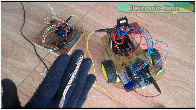
Wireless Hand gesture controlled Robot – In this Tutorial, you will learn how to make a wireless Hand gesture controlled Robot using Arduino, L298N Motor Driver, Flex Sensor, 2 Axis Joystick and 433Mhz RF transmitter and Receiver.
In this project, the Flex sensor will be used as the accelerator while the joystick will be used for controlling the forward, reverse, left and right movements. The Motors speed can be controlled in real-time as we close and open the hand. The robot control system can be activated and de-activated using the Built-in Joystick push Button. The use of Flex Sensor makes this project Hand gesture controlled Robot.
Once the control system is activated, then the flex sensor and joystick together can be used to control the Robot car. Straight fingers mean zero acceleration, so even if you move the joystick the Motors won’t rotate, but as you start bending the flex sensor the motors start rotating, then depending on the amount of the bend the motors speed can be controlled in Real-time.
This is the 3rd version of the Robot Car which I named as the Wireless Hand Gesture Controlled Robot.
While in the 2nd version
Wireless Joystick controlled Robot Car using Arduino, 433Mhz RF, and L298N Motor Driver
In this Project which is based on the Wireless hand gesture controlled robot, I used only the joystick to control the speed and movement of the robot Car. The program used in this project was a little bit complex, so that’s why I decided to make another version of this robot and use a separate sensor for the speed controlling. So that’s why I created version 3.
While in the 1st version
Arduino Project: Bluetooth controlled Robot Car | Phone controlled car + L298N Motor Driver
I used an Android cell phone to control the Robot Car using the HC-05 Bluetooth module.
Let’s get back to our project which is Version 3.
This Tutorial “Version 3”, is based on my previous two tutorials,
in this tutorial I explained, how to assemble the robot parts and how to use the L298N motor driver to control the forward, left, right and reverse movement. In this tutorial, I also explained how to control the speed of a dc motor using the pulse width modulation.
While in this tutorial I explained the joystick Pinout, its basic working principle, its interfacing with Arduino and basic programming to control some leds depending on the movement of the joystick. If you are a beginner and you have never used the Joystick module and L298N motor driver then I highly recommend you should first watch these tutorials and then you can resume from here.
I am sharing a lot of links, and you may find it annoying but trust me, all these videos explain the basics, which will help you in understanding the Connections, Pinout, Interfacing, Programming, checking and so on.
Amazon Purchase Links:
Arduino Nano USB-C Type (Recommended)
433 MHz Transmitter and Receiver Modules:
Other Tools and Components:
ESP32 WiFi + Bluetooth Module (Recommended)
Super Starter kit for Beginners
PCB small portable drill machines
DISCLAIMER:
Please Note: these are affiliate links. I may make a commission if you buy the components through these links. I would appreciate your support in this way!
Interfacing:
All the connections used in this project which is based on the Wireless Hand Gesture Controlled Robot are exactly the same as explained in my previous tutorials. I didn’t even change a single wire. The only modification is on the programming side, which is really easy and I will explain each every instruction.
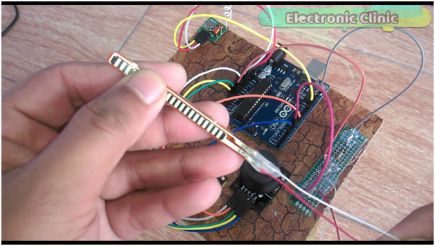
This is the Transmitter Side based on the 433 Mhz RF transmitter and a 2 axis joystick. The wiring is exactly the same as used in the version2. In version 3 I did a very little modification that is I added this small circuit.
And added this Flex sensor which is also known as the bend sensor.
The flex sensor is basically a variable resistor, and its resistance changes as we bend the sensor. The resistance decreases as the bend increases. I have a very detailed getting started tutorial on how to use a flex sensor.
Flex Sensor or bend sensor getting started, circuit, interfacing and Arduino programming
I have also used this sensor In a project based on the human bad posture monitoring system.
Flex sensor or Bend sensor based Human Posture monitoring “Arduino biomedical project”
Article on Human Posture Monitoring using Arduino and Flex Sensor.
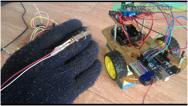
As you can see I have soldered two wires “red and white” with the flex sensor which are connected with the circuit as you can see in the Picture below.
So basically this flex sensor is connected in series with a 10k resistor which makes a voltage divider. The wire from the middle of the flex sensor and 10k resistor is connected with the analog pin A0. The red wire is connected with pin number 6 of the Arduino to provide 5volts to this circuit. While the grey wire is connected with the Arduino’s ground. If you find this confusing you can watch the video given at the end of this Article.
As you can see the flex sensor is fixed on the glove, by opening and closing the hand I can control the amount of bend. Now let’s have a look at the Transmitter and Receiver programming.
Gesture Controlled Robot Arduino Programming:
In this project two Programs are used, one program is written for the Transmitter side and another program is written for the Receiver side. So first let’s start with the Transmitter side. For the Step by Step Programs explanation watch video given at the End. In both the Programs the Virtual Wire library is used which you can download by clicking on the download button below.
Download Library :VirtualWire
Gesture Controlled Transmitter side Programming:
|
1 2 3 4 5 6 7 8 9 10 11 12 13 14 15 16 17 18 19 20 21 22 23 24 25 26 27 28 29 30 31 32 33 34 35 36 37 38 39 40 41 42 43 44 45 46 47 48 49 50 51 52 53 54 55 56 57 58 59 60 61 62 63 64 65 66 67 68 69 70 71 72 73 74 75 76 77 78 79 80 81 82 83 84 85 86 87 88 89 90 91 92 93 94 95 96 97 98 99 100 101 102 103 104 105 106 107 108 109 110 111 112 113 114 115 116 117 118 119 120 121 122 123 124 125 126 127 128 129 130 131 132 133 134 135 136 137 138 139 140 141 142 143 144 145 146 147 148 149 150 151 152 153 154 155 156 157 158 159 160 161 162 163 164 165 166 167 168 169 170 171 172 173 174 175 176 177 178 179 180 |
// Robot Transmitter programming #include <VirtualWire.h> const int transmit_pin = 12; String str; char cstr[100]; String message = ""; unsigned int mlength; // message length // for joystick int flag = 0; int buttonf = 0; int power1 = 6; int power2 = 7; int button = 4; int vrx = A1; int vry = A2; int flexs = A0; int fdata ; int xdata = 0; int ydata = 0; int in1data; int in2data; int in3data; int in4data; void setup() { // Initialise the IO and ISR vw_set_tx_pin(transmit_pin); vw_setup(2000); // Bits per sec Serial.begin(9600); pinMode(vrx, INPUT); pinMode(vry, INPUT); pinMode(flexs, INPUT); pinMode(power1, OUTPUT); pinMode(power2, OUTPUT); digitalWrite(power1, HIGH); digitalWrite(power2, HIGH); pinMode(button, INPUT); digitalWrite(button , HIGH); } void loop() { control(); if( buttonf == 1) { xdata = analogRead(vrx); ydata = analogRead(vry); fdata = analogRead(flexs); fdata = map(fdata, 200,0,0,255); if( fdata < 20 ) { fdata = 0; } if ( (fdata > 20 ) && ( fdata < 50)) { fdata = 50; } if ( (fdata > 50 ) && ( fdata < 100)) { fdata = 100; } if ( (fdata > 100 ) && ( fdata < 150)) { fdata = 150; } if ( (fdata > 150 ) && ( fdata < 200)) { fdata = 200; } if (fdata > 200 ) { fdata = 255; } if ( xdata > 600 ) // forward { in1data = 1; in2data = 0; in3data = 0; in4data = 1; } if ( xdata < 300 ) // reverse { in1data = 0; in2data = 1; in3data = 1; in4data = 0; } if ( ydata > 600 ) // right { in1data = 1; in2data = 0; in3data = 0; in4data = 0; } if ( ydata < 300 ) // left { in1data = 0; in2data = 0; in3data = 0; in4data = 1; } if ( (xdata > 300) && ( xdata < 600 ) && ( ydata > 300) && ( ydata < 600) ) { in1data = 0; in2data = 0; in3data = 0; in4data = 0; } //Serial.println(xdata); //Serial.println(ydata); SendData(in1data,in2data,in3data,in4data,buttonf,fdata); //delay(100); } if(buttonf == 0) { SendData(0,0,0,0,0,0); // send 0 to the receiver. delay(100); } } // this function takes 5 arguments as the input // the sensors and the sensors group number. // let's say we are using multiple sensors, the sensors //can be divided into groups. void SendData( int value1,int value2,int value3, int value4, int buttonstatus, int mspeed) { message = message + value1 +"," + value2 + "," + value3 + "," + value4 + "," + buttonstatus +"," +mspeed; Serial.println(message); mlength = message.length(); // find the number of characters in a message. str = message; str.toCharArray(cstr,100); vw_send((uint8_t *)cstr, mlength); // vw_wait_tx(); // Wait until the whole message is gone str = ""; message = ""; } void control() { if (( digitalRead(button) == LOW ) && (buttonf == 0)) { Serial.println(" Started"); buttonf = 1; delay(1000); } if (( digitalRead(button) == LOW ) && (buttonf == 1)) { Serial.println("ended"); buttonf = 0; delay(1000); } digitalWrite(button , HIGH); } |
Gesture controlled Receiver Side Programming:
|
1 2 3 4 5 6 7 8 9 10 11 12 13 14 15 16 17 18 19 20 21 22 23 24 25 26 27 28 29 30 31 32 33 34 35 36 37 38 39 40 41 42 43 44 45 46 47 48 49 50 51 52 53 54 55 56 57 58 59 60 61 62 63 64 65 66 67 68 69 70 71 72 73 74 75 76 77 78 79 80 81 82 83 84 85 86 87 88 89 90 91 92 93 94 95 96 97 98 99 100 101 102 103 104 105 106 107 108 109 110 111 112 113 114 115 116 117 118 119 120 121 122 123 124 125 126 127 128 129 130 131 132 133 134 135 136 137 138 139 140 141 142 143 144 145 146 147 148 149 150 151 152 153 154 155 156 157 158 159 160 161 162 163 164 165 166 167 168 169 170 171 172 173 174 175 176 177 178 179 180 181 182 183 184 185 186 187 188 189 190 191 192 193 194 195 196 197 198 199 200 201 202 203 204 205 206 207 208 209 210 211 212 213 214 215 216 217 218 219 220 221 222 223 |
// receiver Programming #include <VirtualWire.h> const int receive_pin = 3; String message; String myString; // for joystick int xvalue; int yvalue; int buttonf; int in1data; int in2data; int in3data; int in4data; int mspeed; int bfdata; // buttonflag int fahad; // for L298N motor driver int ena = 5; int enb = 6; int in1 = 8; int in2 = 9; int in3 = 10; int in4 = 11; int sf = 0; void setup() { delay(1000); Serial.begin(9600); // Debugging only pinMode(ena, OUTPUT); pinMode(enb, OUTPUT); pinMode(in1, OUTPUT); pinMode(in2, OUTPUT); pinMode(in3, OUTPUT); pinMode(in4, OUTPUT); analogWrite(ena, 255); analogWrite(enb, 255); delay(1000); Serial.println("setup"); // Initialise the IO and ISR vw_set_rx_pin(receive_pin); vw_set_ptt_inverted(true); // Required for DR3100 vw_setup(2000); // Bits per sec vw_rx_start(); // Start the receiver PLL running } void loop() { rfreceive(); String l = getValue(myString, ',', 0); // in1 String m = getValue(myString, ',', 1); // in2 String n = getValue(myString, ',', 2); // in3 String o = getValue(myString, ',', 3); // in4 String p = getValue(myString, ',', 4); // buttonf String q = getValue(myString, ',', 5); // mspeed in1data = l.toInt(); in2data = m.toInt(); in3data = n.toInt(); in4data = o.toInt(); bfdata = p.toInt(); mspeed = q.toInt(); /* // print received data Serial.println(in1data); Serial.println(in2data); Serial.println(in3data); Serial.println(in4data); Serial.println(bfdata); Serial.println(mspeed); */ if ( bfdata == 0) { // Serial.println("stopped"); analogWrite(ena,0); analogWrite(enb,0); digitalWrite(in1,LOW); digitalWrite(in2, LOW); digitalWrite(in3,LOW); digitalWrite(in3,LOW); } if ( ( in1data == 0 ) && (in2data == 0 ) && (in3data == 0) && (in4data == 0) && ( bfdata == 1) ) { analogWrite(ena, 0); analogWrite(enb,0); //Serial.println("STOPPED"); digitalWrite(in1,LOW); digitalWrite(in2, LOW); digitalWrite(in3,LOW); digitalWrite(in4,LOW); } if ( ( in1data == 1 ) && (in2data== 0 ) && (in3data == 0) && (in4data == 1) && ( bfdata == 1) ) { // Serial.println("Forward"); analogWrite(ena, mspeed); analogWrite(enb,mspeed); digitalWrite(in1,HIGH); digitalWrite(in2, LOW); digitalWrite(in3,LOW); digitalWrite(in4,HIGH); } if ( ( in1data == 0 ) && (in2data== 1 ) && (in3data == 1) && (in4data == 0) && ( bfdata == 1) ) { //Serial.println("Reverse"); analogWrite(ena, mspeed); analogWrite(enb,mspeed); digitalWrite(in1,LOW); digitalWrite(in2, HIGH); digitalWrite(in3,HIGH); digitalWrite(in4,LOW); } if ( ( in1data == 1 ) && (in2data== 0 ) && (in3data == 0) && (in4data == 0) && ( bfdata == 1) ) { // Serial.println("RIGHT"); analogWrite(ena, mspeed); analogWrite(enb,mspeed); digitalWrite(in1,HIGH); digitalWrite(in2, LOW); digitalWrite(in3,LOW); digitalWrite(in4,LOW); } if ( ( in1data == 0 ) && (in2data== 0 ) && (in3data == 0) && (in4data == 1) && ( bfdata == 1) ) { // Serial.println("left"); analogWrite(ena, mspeed); analogWrite(enb,mspeed); digitalWrite(in1,LOW); digitalWrite(in2, LOW); digitalWrite(in3,LOW); digitalWrite(in4,HIGH); } //in1data = 0; //in2data = 0; //in3data = 0; //in4data = 0; //bfdata = 0; } String getValue(String data, char separator, int index) { int found = 0; int strIndex[] = { 0, -1 }; int maxIndex = data.length() - 1; for (int i = 0; i <= maxIndex && found <= index; i++) { if (data.charAt(i) == separator || i == maxIndex) { found++; strIndex[0] = strIndex[1] + 1; strIndex[1] = (i == maxIndex) ? i+1 : i; } } return found > index ? data.substring(strIndex[0], strIndex[1]) : ""; } void rfreceive() { uint8_t buf[VW_MAX_MESSAGE_LEN]; uint8_t buflen = VW_MAX_MESSAGE_LEN; if (vw_get_message(buf, &buflen)) // Non-blocking { int i; // Message with a good checksum received, dump it. //Serial.print("Got: "); for (i = 0; i < buflen; i++) { char c = (buf[i]); message = message + c ; // make a message from the received characters } myString = message; Serial.println(message); // delay(1000); message = ""; } } |


