Arduino i2c Scanner and Multiple i2c Sensors Interfacing & Programming
Last Updated on August 18, 2024 by Engr. Shahzada Fahad
Table of Contents
Description:
Arduino i2c Scanner and Multiple i2c Sensors Interfacing & Programming– in this tutorial, I will teach you the simplest method on how to scan the address of an i2c supported Sensor and how to connect multiple i2c supported sensors with Arduino without using the Sensors addresses. There are situations when we need to use multiple sensors with the Arduino Uno, but due to the limited number of the I/O pins we are not able to connect many sensors, but thanks to the i2c supported Sensors, now we can connect multiple i2c sensors using only two wires. In this tutorial, I will practically demonstrate; how to use the BPM180 and HMC588L with the Arduino.
I searched Google and YouTube, I found so many tutorials but they were talking about the sensors addresses and they were rewriting the entire code, reading and writing the hex codes, performing all calculations and so on. Almost all the i2c supported sensors have libraries and programmers has made it very simple for us, we only read the values by calling certain built-in functions. So today you will learn how to use i2c supported sensors without using the addresses.
In this tutorial, I will cover
- i2c bus Explanation
- BMP180 Sensor Introduction, its Pinout, interfacing programming and testing
- HMC5883l Sensor Introduction, Pinout, interfacing, programming and testing
- Combining both the Sensors and access the data of each sensor separately.
Without any further delay let’s get started!!!
Amazon Links:
Arduino Nano USB-C Type (Recommended)
*Disclosure: These are affiliate links. As an Amazon Associate I earn from qualifying purchases.
Before I am going to explain the multiple Sensors interfacing, I would like to explain some basics. I will write programs for the BMP180 and HMC588L Sensors; once I explain the basics then I will write a combined program.
I2C Bus:
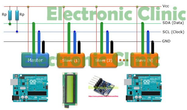
I2C communication Bus has become very popular and now commonly used by thousands of electronics devices because of its easy implementation. By the easy implementation I mean that such devices need only 2 wires. This way we can connect so many devices with for example Arduino using only two wires. Using I2C communication bus we can connect many devices at the same time using only two wires as each device has its own unique address. In Arduino Uno the i2c bus is available on pins A4 and A5.
Arduino i2c Scanner Program:
While the i2c supported Sensor is connected with the Arduino, the following program can be used to find the i2c address of any i2c supported sensor.
All the libraries used in this tutorial can be downloaded by clicking on the link given below.
|
1 2 3 4 5 6 7 8 9 10 11 12 13 14 15 16 17 18 19 20 21 22 23 24 25 26 27 28 29 30 31 32 33 34 35 36 37 38 39 40 41 42 43 44 45 46 47 48 49 50 51 52 53 54 55 56 57 58 59 60 61 62 63 64 65 66 67 68 69 70 71 72 73 74 75 76 77 78 79 80 81 82 83 84 85 86 87 88 89 90 91 92 93 94 95 96 97 98 99 100 101 102 103 104 105 106 107 108 109 110 111 112 113 114 115 116 117 118 119 120 121 122 123 124 125 126 127 128 129 130 131 132 133 134 135 136 137 138 139 140 141 142 143 144 145 146 147 148 149 150 151 152 153 154 155 156 157 158 159 160 161 162 163 164 165 166 167 168 169 170 171 172 173 174 175 176 177 178 179 180 181 182 183 184 185 186 187 188 189 190 191 192 193 194 195 196 |
#include <Wire.h> #include <Arduino.h> // scans devices from 50 to 800KHz I2C speeds. // lower than 50 is not possible long speed[] = { 50, 100, 200, 250, 400, 500, 800 }; const int speeds = sizeof(speed)/sizeof(speed[0]); // DELAY BETWEEN TESTS #define RESTORE_LATENCY 5 // for delay between tests of found devices. bool delayFlag = false; // MINIMIZE OUTPUT bool printAll = true; bool header = true; // STATE MACHINE enum states { STOP, ONCE, CONT, HELP }; states state = STOP; uint32_t startScan; uint32_t stopScan; void setup() { Serial.begin(115200); Wire.begin(); displayHelp(); } void loop() { switch (getCommand()) { case 's': state = ONCE; break; case 'c': state = CONT; break; case 'd': delayFlag = !delayFlag; Serial.print(F("<delay=")); Serial.println(delayFlag?F("5>"):F("0>")); break; case 'e': // eeprom test TODO break; case 'h': header = !header; Serial.print(F("<header=")); Serial.println(header?F("yes>"):F("no>")); break; case '?': state = HELP; break; case 'p': printAll = !printAll; Serial.print(F("<print=")); Serial.println(printAll?F("all>"):F("found>")); break; case 'q': state = HELP; break; default: break; } switch(state) { case ONCE: I2Cscan(); state = HELP; break; case CONT: I2Cscan(); delay(1000); break; case HELP: displayHelp(); state = STOP; break; case STOP: break; default: // ignore all non commands break; } } char getCommand() { char c = '\0'; if (Serial.available()) { c = Serial.read(); } return c; } void displayHelp() { Serial.println(F("\nArduino I2C Scanner - 0.1.03\n")); Serial.println(F("\ts = single scan")); Serial.println(F("\tc = continuous scan - 1 second delay")); Serial.println(F("\tq = quit continuous scan")); Serial.println(F("\td = toggle latency delay between successful tests.")); Serial.println(F("\tp = toggle printAll - printFound.")); Serial.println(F("\th = toggle header - noHeader.")); Serial.println(F("\t? = help - this page")); Serial.println(); } void I2Cscan() { startScan = millis(); uint8_t count = 0; if (header) { Serial.print(F("TIME\tDEC\tHEX\t")); for (uint8_t s = 0; s < speeds; s++) { Serial.print(F("\t")); Serial.print(speed[s]); } Serial.println(F("\t[KHz]")); for (uint8_t s = 0; s < speeds + 5; s++) { Serial.print(F("--------")); } Serial.println(); } // TEST // 0.1.04: tests only address range 8..120 // -------------------------------------------- // Address R/W Bit Description // 0000 000 0 General call address // 0000 000 1 START byte // 0000 001 X CBUS address // 0000 010 X reserved - different bus format // 0000 011 X reserved - future purposes // 0000 1XX X High Speed master code // 1111 1XX X reserved - future purposes // 1111 0XX X 10-bit slave addressing for (uint8_t address = 8; address < 120; address++) { bool printLine = printAll; bool found[speeds]; bool fnd = false; for (uint8_t s = 0; s < speeds ; s++) { TWBR = (F_CPU/(speed[s]*1000) - 16)/2; Wire.beginTransmission (address); found[s] = (Wire.endTransmission () == 0); fnd |= found[s]; // give device 5 millis if (fnd && delayFlag) delay(RESTORE_LATENCY); } if (fnd) count++; printLine |= fnd; if (printLine) { Serial.print(millis()); Serial.print(F("\t")); Serial.print(address, DEC); Serial.print(F("\t0x")); Serial.print(address, HEX); Serial.print(F("\t")); for (uint8_t s = 0; s < speeds ; s++) { Serial.print(F("\t")); Serial.print(found[s]? F("V"):F(".")); } Serial.println(); } } stopScan = millis(); if (header) { Serial.println(); Serial.print(count); Serial.print(F(" devices found in ")); Serial.print(stopScan - startScan); Serial.println(F(" milliseconds.")); } } |
About the HMC5883L i2c supported Sensor:
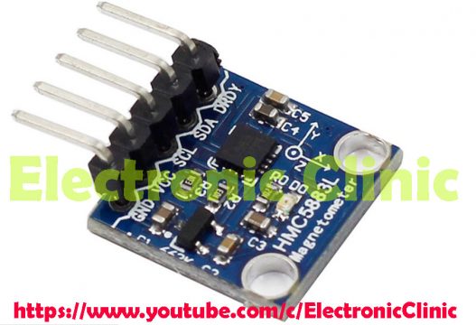
The module includes a state-of-the-art, High-Resolution HMC118x series magneto-resistive sensor, Plus an ASIC containing amplification, Automatic degaussing strap Drivers, Offset cancellation, and a 12-bit ADC that enables 1 to 2 degree compass heading accuracy. The I2C serial bus allows for easy interface.
Features:
- The Honeywell HMC5883L is a surface mount, multi-chip module designed for low-field magnetic sensing with a digital interface for applications such as low cost compassing and magnetometry.
- The 12-Bit ADC coupled with low noise AMR sensors
- Low voltage operations and low power consumption, supports built in self test.
- Built in strap drive circuits, wide magnetic field range,I2C digital interface
- Working voltage 3.3v to 5v.
HMC5883L Connection to Arduino:
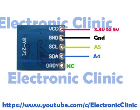
- Arduino GND -> HMC5883L GND
- Arduino 3.3V -> HMC5883L VCC
- Arduino A4 (SDA) -> HMC5883L SDA
- Arduino A5 (SCL) -> HMC5883L SCL
HMC5883L Arduino Code:
The libraries used in this program can be downloaded by clicking on the following link.
|
1 2 3 4 5 6 7 8 9 10 11 12 13 14 15 16 17 18 19 20 21 22 23 24 25 26 27 28 29 30 31 32 33 34 35 36 37 38 39 40 41 42 43 44 45 46 47 48 49 50 51 52 53 54 55 56 57 58 59 60 61 62 63 64 65 66 67 68 69 70 71 72 73 74 75 76 77 78 79 80 81 82 83 84 85 86 87 88 89 90 91 92 93 94 95 96 97 98 99 100 101 102 103 104 105 106 107 108 109 110 111 112 113 114 115 116 117 118 119 120 |
/* HMC5883L_Example.pde - Example sketch for integration with an HMC5883L triple axis magnetomerwe. This program is free software: you can redistribute it and/or modify it under the terms of the version 3 GNU General Public License as published by the Free Software Foundation. This program is distributed in the hope that it will be useful, but WITHOUT ANY WARRANTY; without even the implied warranty of MERCHANTABILITY or FITNESS FOR A PARTICULAR PURPOSE. See the GNU General Public License for more details. You should have received a copy of the GNU General Public License along with this program. If not, see <http://www.gnu.org/licenses/>. */ // Reference the I2C Library #include <Wire.h> // Reference the HMC5883L Compass Library #include <HMC5883L.h> // Store our compass as a variable. HMC5883L compass; // Record any errors that may occur in the compass. int error = 0; int ledpin = 13; // Out setup routine, here we will configure the microcontroller and compass. void setup() { // Initialize the serial port. Serial.begin(9600); pinMode(ledpin, OUTPUT); Serial.println("Starting the I2C interface."); Wire.begin(); // Start the I2C interface. Serial.println("Constructing new HMC5883L"); compass = HMC5883L(); // Construct a new HMC5883 compass. Serial.println("Setting scale to +/- 1.3 Ga"); error = compass.SetScale(1.3); // Set the scale of the compass. if(error != 0) // If there is an error, print it out. Serial.println(compass.GetErrorText(error)); Serial.println("Setting measurement mode to continous."); error = compass.SetMeasurementMode(Measurement_Continuous); // Set the measurement mode to Continuous if(error != 0) // If there is an error, print it out. Serial.println(compass.GetErrorText(error)); } // Our main program loop. void loop() { // Retrive the raw values from the compass (not scaled). MagnetometerRaw raw = compass.ReadRawAxis(); // Retrived the scaled values from the compass (scaled to the configured scale). MagnetometerScaled scaled = compass.ReadScaledAxis(); // Values are accessed like so: int MilliGauss_OnThe_XAxis = scaled.XAxis;// (or YAxis, or ZAxis) // Calculate heading when the magnetometer is level, then correct for signs of axis. float heading = atan2(scaled.YAxis, scaled.XAxis); // Once you have your heading, you must then add your 'Declination Angle', which is the 'Error' of the magnetic field in your location. // Find yours here: http://www.magnetic-declination.com/ // Mine is: 2� 37' W, which is 2.617 Degrees, or (which we need) 0.0456752665 radians, I will use 0.0457 // If you cannot find your Declination, comment out these two lines, your compass will be slightly off. float declinationAngle = 0.0457; heading += declinationAngle; // Correct for when signs are reversed. if(heading < 0) heading += 2*PI; // Check for wrap due to addition of declination. if(heading > 2*PI) heading -= 2*PI; // Convert radians to degrees for readability. float headingDegrees = heading * 180/M_PI; // Output the data via the serial port. Output(raw, scaled, heading, headingDegrees); // Normally we would delay the application by 66ms to allow the loop // to run at 15Hz (default bandwidth for the HMC5883L). // However since we have a long serial out (104ms at 9600) we will let // it run at its natural speed. // delay(66); } // Output the data down the serial port. void Output(MagnetometerRaw raw, MagnetometerScaled scaled, float heading, float headingDegrees) { Serial.print("Raw:\t"); Serial.print(raw.XAxis); Serial.print(" "); Serial.print(raw.YAxis); Serial.print(" "); Serial.print(raw.ZAxis); Serial.print(" \tScaled:\t"); Serial.print(scaled.XAxis); Serial.print(" "); Serial.print(scaled.YAxis); Serial.print(" "); Serial.print(scaled.ZAxis); Serial.print(" \tHeading:\t"); Serial.print(heading); Serial.print(" Radians \t"); Serial.print(headingDegrees); Serial.println(" Degrees \t"); //delay(1000); if((headingDegrees >=1)&(headingDegrees <= 45) ) digitalWrite(ledpin,HIGH); else digitalWrite(ledpin,LOW); } |
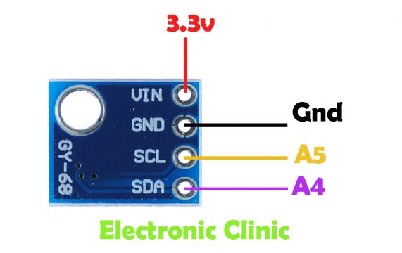
About the BMP180 i2c supported Sensor:
The BMP180 Barometric Pressure Sensor is one of the most commonly used Sensors throughout the world. This Sensor is often used in student’s projects. With the help of the BMP180 Barometric Pressure Sensor which is an i2c supported Sensor, we can find the Temperature, Pressure and Altitude. I have already used this Sensor in an IoT based project using Nodemcu ESP8266 Wifi module and Blynk application. You can find link in the related projects section. The BMP180 i2c supported Sensor interfacing with the Arduino is very simple. We need only two wires to connect this sensor with the Arduino Uno. Let’s have a look at the following Connection diagram.
BMP180 Sensor connection to Arduino:
BMP180 Arduino Uno Code:
|
1 2 3 4 5 6 7 8 9 10 11 12 13 14 15 16 17 18 19 20 21 22 23 24 25 26 27 28 29 30 31 32 33 34 35 36 37 38 39 40 41 42 43 44 45 46 47 48 49 50 51 52 53 |
#include <Wire.h> #include <Adafruit_BMP085.h> // Connect VCC of the BMP180 / BMP085 sensor to 3.3V // Connect GND to Ground // Connect SCL to i2c clock - on '168/'328 Arduino Uno/Duemilanove/etc thats Analog 5 // Connect SDA to i2c data - on '168/'328 Arduino Uno/Duemilanove/etc thats Analog 4 // EOC is not used, it signifies an end of conversion // XCLR is a reset pin, also not used here Adafruit_BMP085 bmp; void setup() { Serial.begin(9600); if (!bmp.begin()) { Serial.println("Could not find a valid BMP180 sensor, check wiring!"); while (1) {} } } void loop() { Serial.print("Temperature = "); Serial.print(bmp.readTemperature()); Serial.println(" *C"); Serial.print("Pressure = "); Serial.print(bmp.readPressure()); Serial.println(" Pa"); // Calculate altitude assuming 'standard' barometric // pressure of 1013.25 millibar = 101325 Pascal Serial.print("Altitude = "); Serial.print(bmp.readAltitude()); Serial.println(" meters"); Serial.print("Pressure at sealevel (calculated) = "); Serial.print(bmp.readSealevelPressure()); Serial.println(" Pa"); // you can get a more precise measurement of altitude // if you know the current sea level pressure which will // vary with weather and such. If it is 1015 millibars // that is equal to 101500 Pascals. // for my area, my city name is Nowshera. // air pressure over here is 1006millibars which is equal to 100600 pascal Serial.print("Real altitude = "); Serial.print(bmp.readAltitude(100600)); Serial.println(" meters"); Serial.println(); delay(500); } |
So now that I have explained the connection of both the Sensors with the Arduino Uno and I also share the codes. Now it’s time to combine both the projects. As both the Sensors HMC5883L and BMP180 supports the i2c communication. So, both the sensors can be connected with Arduino’s pins A4 and A5. Connect the SDA pins of both the sensors with the A4 of the Arduino Uno and also connect the SCL pins of both the Sensors with the A5 pin of the Arduino Uno.
Multiple i2c devices Arduino code:
Before you start the programming first of all, make sure you download the libraries, these libraries can be downloaded by clicking on the following link.
This program is the combination of the programs given above. We don’t need to use the addresses of the modules; this task has already been done by the programmers, now we only need to use these libraries.
|
1 2 3 4 5 6 7 8 9 10 11 12 13 14 15 16 17 18 19 20 21 22 23 24 25 26 27 28 29 30 31 32 33 34 35 36 37 38 39 40 41 42 43 44 45 46 47 48 49 50 51 52 53 54 55 56 57 58 59 60 61 62 63 64 65 66 67 68 69 70 71 72 73 74 75 76 77 78 79 80 81 82 83 84 85 86 87 88 89 90 91 92 93 94 95 96 97 98 99 100 101 102 103 104 105 106 107 108 109 110 111 112 113 114 115 116 117 118 119 120 121 122 123 124 125 126 127 128 129 130 131 132 133 134 135 136 137 138 139 140 141 142 143 144 145 146 147 148 149 150 151 152 153 154 155 156 157 158 159 160 161 162 163 164 165 166 167 168 169 170 171 172 173 174 175 176 177 |
#include <Wire.h> #include <Adafruit_BMP085.h> #include <HMC5883L.h> // Connect VCC of the BMP180 / BMP085 sensor to 3.3V // Connect GND to Ground // Connect SCL to i2c clock - on '168/'328 Arduino Uno/Duemilanove/etc thats Analog 5 // Connect SDA to i2c data - on '168/'328 Arduino Uno/Duemilanove/etc thats Analog 4 // EOC is not used, it signifies an end of conversion // XCLR is a reset pin, also not used here Adafruit_BMP085 bmp; // Store our compass as a variable. HMC5883L compass; // Record any errors that may occur in the compass. int error = 0; int ledpin = 13; void setup() { Serial.begin(9600); } void loop() { Serial.println("bmp data"); bmp180sensor(); delay(2000); Serial.println("hmc5883l data"); hmc5883lsensor(); Serial.println(); delay(2000); } void bmp180sensor() { Wire.begin(); // Wire.endTransmission(); if (!bmp.begin()) { Serial.println("Could not find a valid BMP180 sensor, check wiring!"); while (1) {} } Serial.print("Temperature = "); Serial.print(bmp.readTemperature()); Serial.println(" *C"); Serial.print("Pressure = "); Serial.print(bmp.readPressure()); Serial.println(" Pa"); // Calculate altitude assuming 'standard' barometric // pressure of 1013.25 millibar = 101325 Pascal Serial.print("Altitude = "); Serial.print(bmp.readAltitude()); Serial.println(" meters"); Serial.print("Pressure at sealevel (calculated) = "); Serial.print(bmp.readSealevelPressure()); Serial.println(" Pa"); // you can get a more precise measurement of altitude // if you know the current sea level pressure which will // vary with weather and such. If it is 1015 millibars // that is equal to 101500 Pascals. // for my area, my city name is Nowshera. // air pressure over here is 1006millibars which is equal to 100600 pascal Serial.print("Real altitude = "); Serial.print(bmp.readAltitude(100600)); Serial.println(" meters"); Serial.println(); delay(500); Wire.endTransmission(); } void hmc5883lsensor() { int flag = 0 ; if ( flag == 0 ) { pinMode(ledpin, OUTPUT); // Serial.println("Starting the I2C interface."); Wire.begin(); // Start the I2C interface. //Serial.println("Constructing new HMC5883L"); compass = HMC5883L(); // Construct a new HMC5883 compass. Serial.println("Setting scale to +/- 1.3 Ga"); error = compass.SetScale(1.3); // Set the scale of the compass. if(error != 0) // If there is an error, print it out. Serial.println(compass.GetErrorText(error)); // Serial.println("Setting measurement mode to continous."); error = compass.SetMeasurementMode(Measurement_Continuous); // Set the measurement mode to Continuous if(error != 0) // If there is an error, print it out. Serial.println(compass.GetErrorText(error)); flag = 1; } // Retrive the raw values from the compass (not scaled). MagnetometerRaw raw = compass.ReadRawAxis(); // Retrived the scaled values from the compass (scaled to the configured scale). MagnetometerScaled scaled = compass.ReadScaledAxis(); // Values are accessed like so: int MilliGauss_OnThe_XAxis = scaled.XAxis;// (or YAxis, or ZAxis) // Calculate heading when the magnetometer is level, then correct for signs of axis. float heading = atan2(scaled.YAxis, scaled.XAxis); // Once you have your heading, you must then add your 'Declination Angle', which is the 'Error' of the magnetic field in your location. // Find yours here: http://www.magnetic-declination.com/ // Mine is: 2� 37' W, which is 2.617 Degrees, or (which we need) 0.0456752665 radians, I will use 0.0457 // If you cannot find your Declination, comment out these two lines, your compass will be slightly off. float declinationAngle = 0.0457; heading += declinationAngle; // Correct for when signs are reversed. if(heading < 0) heading += 2*PI; // Check for wrap due to addition of declination. if(heading > 2*PI) heading -= 2*PI; // Convert radians to degrees for readability. float headingDegrees = heading * 180/M_PI; // Output the data via the serial port. Output(raw, scaled, heading, headingDegrees); // Normally we would delay the application by 66ms to allow the loop // to run at 15Hz (default bandwidth for the HMC5883L). // However since we have a long serial out (104ms at 9600) we will let // it run at its natural speed. // delay(66); } // Output the data down the serial port. void Output(MagnetometerRaw raw, MagnetometerScaled scaled, float heading, float headingDegrees) { /* Serial.print("Raw:\t"); Serial.print(raw.XAxis); Serial.print(" "); Serial.print(raw.YAxis); Serial.print(" "); Serial.print(raw.ZAxis); Serial.print(" \tScaled:\t"); Serial.print(scaled.XAxis); Serial.print(" "); Serial.print(scaled.YAxis); Serial.print(" "); Serial.print(scaled.ZAxis); */ Serial.print(" \tHeading:\t"); Serial.print(heading); Serial.print(" Radians \t"); Serial.print(headingDegrees); Serial.println(" Degrees \t"); //delay(1000); if((headingDegrees >=1)&(headingDegrees <= 45) ) digitalWrite(ledpin,HIGH); else digitalWrite(ledpin,LOW); Wire.endTransmission(); } |
Watch Video for the Practical Demonstration:
Discover more from Electronic Clinic
Subscribe to get the latest posts sent to your email.


