Arduino IOT Project: watering plants and soil moisture monitoring
Last Updated on August 18, 2024 by Engr. Shahzada Fahad
Table of Contents
soil moisture monitoring:
watering plants and soil moisture monitoring- This is an iot based project designed for monitoring the Soil moisture and controlling the Solenoid valve from anywhere around the world. The soil moisture is monitored using the Blynk application. This project is based on the Nodemcu esp8266 wifi module, soil moisture sensor, Solenoid Valve, and Arduino Uno or Mega.
In this project two-way communication is used, we can monitor the soil moisture and also control the Solenoid valve in Realtime.
If you are working on the moisture sensor for the first time then I recommend you should watch my getting started tutorial on the moisture sensor, in which I explained all the basics, including the moisture sensors modes “digital and analog” , the purpose of the potentiometer and LEDs, the basic circuit connections and programming explaining everything.
Recently, I posted another advanced level project based on Irrigation. In this project I used the Lora transceiver modules with the Nodemcu ESP8266. The Nodemcu ESP8266 module in this project is used as the Wifi Gateway.
You can also ready my article on IoT based Water level monitoring and automatic water pump control system using the ESP32 WiFi + Bluetooth Module, Waterproof Ultrasonic Sensor, and the New Blynk V2.0 more…
Amazon Links:
Arduino Nano USB-C Type (Recommended)
*Disclosure: These are affiliate links. As an Amazon Associate I earn from qualifying purchases.
IoT Soil Moisture Monitoring Project Circuit Diagram:

9.1.0 version of the cadsoft eagle software is used for making the schematic. The Nodemcu module tx and Rx pins are connected with pin2 and pin3 of the Arduino. while the Vin pin of the Nodemcu module is connected with the output of the voltage regulator. This is a regulated 5v power supply based on the lm7805 voltage regulator. Two 470uf capacitors are connected at the input and output side of the regulator. A 330-ohm resistor is connected in series with a 2.5v led. This is a current limiting resistor. while J1 is a dc female socket, over here you can connect a 12v adaptor or battery. But you can also power up the Nodemcu module using your laptop USB port. But in my case, I am going to use a 12v adaptor.
The soil moisture Sensor VCC pin is connected with Arduino’s 5v, the ground is connected with the Arduino’s ground while the A0 pin of the moisture sensor which is the analog output pin of the moisture sensor is connected with the Arduino’s analog pin A1. While the digital output pin of the moisture sensor is not connected. While the remaining two pins are connected with the two-legged lead.
These two relays will be used to control the Solenoid valve and the water pump.
For controlling these relays we will need relay drivers, the relay drivers simply consists of the 2n2222 NPN transistors, 10k resistors, and diodes. As you can see a 10k resistor is connected with the base of 2n2222 NPN transistor as it’s a BJT “bipolar junction transistor” a current controlled device, that’s why we need a current limiting resistor. We usually use a 10k resistor. The emitter of the 2n2222 NPN transistor is connected with the ground while the collector is connected with one side of the relay coil, while the other side of the relay coil is connected with 12volts. This relay can be energized and de-energized using this transistor. As you can see this relay consists of 5 pins, two coil pins, common, normally closed and normally open. These three pins have no physical connection with the coil pins…. In my previous tutorial based on home automation using Nodemcu and Blynk application, I have explained this in very detail, and in that tutorial, I also explained how to connect a lamp or any other load with the relays output watch video tutorial on my YouTube channel. All the connections are exactly the same. These are freewheeling diodes, used against back emf protection.
Note: this old version of the Blynk app is no more functional. For the blynk mobile App setup and Blynk.cloud dashboard setup ready my article on the New Blynk V2.0. In this article I have explained how to migrate your projects from Blynk 1.0 to the new Blynk V2.0. You can also watch the video.
Blynk application Designing for monitoring Soil Moisture:
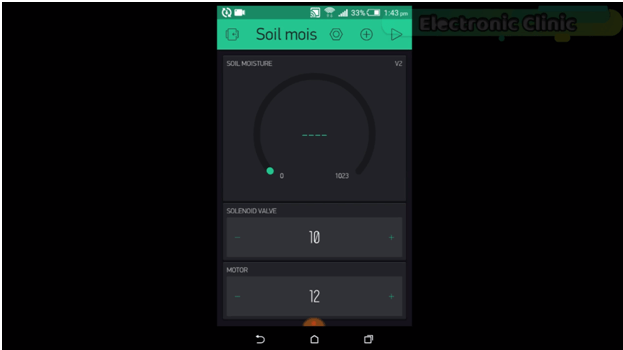
Follow the following steps or watch video at the end of this Article for the best understanding.
- First of all, open the blynk application
- set the project name as Soil Moisture.
- Click on the choose device and select Nodemcu and make sure you set the connection type to wifi and then click on the create button, an authentication token will be sent on your email id, which will be then used in programming, simply copy and paste it in programming.
- Click anywhere on the screen and search for the gauge and add it, click on the gauge and set the name as Soil Moisture. now click on the pin and select virtual and select v2. Set the maximum value to 1023, change the font then click on the push and select 1 second.
- now click on the screen and add two numeric input buttons which will be used for controlling the solenoid valve and water pump……click on the numeric input…set the name as solenoid valve….click pin and select the virtual pin10…set the minimum value to 10 and the maximum value to 11.these 10 and 11 values will be used to control the relay connected with pin13 of the Arduino. …now repeat the same steps for other numeric input button.
IoT plants watering system Programming:
In this project two programs are used, one program is written for the Arduino, while another program is written for the Nodemcu esp8266 wifi module.
Soil Moisture Sensor Arduino Programming:
|
1 2 3 4 5 6 7 8 9 10 11 12 13 14 15 16 17 18 19 20 21 22 23 24 25 26 27 28 29 |
#include <SoftwareSerial.h> SoftwareSerial nodemcu(2,3); int msensor = A1; // moisture sensor is connected with the analog pin A1 of the Arduino int msvalue = 0; // moisture sensor value long int data; int relay1 = 13; // to control the solenoid value int relay2 = 12; // to control the motor or anything else int sdata1 = 0; // Moisture sensor value String cdata; // complete data void setup() { Serial.begin(9600); nodemcu.begin(9600); pinMode(msensor, INPUT); pinMode(relay1, OUTPUT); pinMode(relay2, OUTPUT); } void loop() { |
we simply ready the moisture using the analogread function and store the value in variable msvalue. Then using the serial.println function the value is send to the serial monitor for the debugging purposes and then save the value in variable sdata1. And then add the value of this variable with the cdata and use comma as the delimeter for separating the sensor value. Then we send the complete message to the Nodemcu module and use a delay of 1 second and then at the end empty the cdata variable for storing new values.
|
1 2 3 4 5 6 7 8 9 10 11 12 13 14 15 16 17 18 19 20 21 22 23 24 25 26 27 28 29 30 31 32 33 34 35 36 37 38 39 40 41 42 43 44 45 |
if(nodemcu.available() == 0 ) { msvalue = analogRead(msensor); Serial.println(msvalue); sdata1 = msvalue; cdata = cdata + sdata1+","; Serial.println(cdata); nodemcu.println(cdata); delay(1000); // 1000 milli seconds cdata = ""; } if ( nodemcu.available() > 0 ) { data = nodemcu.parseInt(); delay(100); Serial.println(data); if ( data == 10 ) { digitalWrite(relay1, LOW); } if ( data == 11 ) { digitalWrite(relay1, HIGH); } // relay2 if ( data == 12 ) { digitalWrite(relay2, LOW); } if ( data == 13 ) { digitalWrite(relay2, HIGH); } } } |
Nodemcu esp8266 wifi module programming:
|
1 2 3 4 5 6 7 8 9 10 11 12 13 14 15 16 17 18 19 20 21 22 23 24 25 26 27 28 29 30 31 32 33 34 35 36 37 38 39 40 41 42 43 44 45 46 47 48 49 50 51 52 53 54 55 56 57 58 59 60 61 62 63 64 65 66 67 68 69 70 71 72 73 74 75 76 77 78 79 80 81 82 83 84 85 86 87 88 89 90 91 92 93 94 95 96 97 98 99 100 101 102 103 104 105 106 107 108 109 110 111 112 113 114 115 116 117 118 119 120 121 122 123 124 125 126 127 |
#define BLYNK_PRINT Serial #include <ESP8266WiFi.h> #include <BlynkSimpleEsp8266.h> #include <SoftwareSerial.h> #include <SimpleTimer.h> int pinValue1; int pinValue2; int pinValue3; int pinValue4; char auth[] = "bc089973710d40fa8640cd9c290bb040"; // Your WiFi credentials. // Set password to "" for open networks. char ssid[] = "ZONG MBB-E8231-6E63"; char pass[] = "08659650"; SimpleTimer timer; String myString; // complete message from arduino, which consistors of snesors data char rdata; // received charactors //for soild moisture int firstVal ; // This function sends Arduino's up time every second to Virtual Pin (1). // In the app, Widget's reading frequency should be set to PUSH. This means // that you define how often to send data to Blynk App. void myTimerEvent() { // You can send any value at any time. // Please don't send more that 10 values per second. Blynk.virtualWrite(V1, millis() / 1000); } void setup() { // Debug console Serial.begin(9600); Blynk.begin(auth, ssid, pass); timer.setInterval(1000L,sensorvalue1); } void loop() { if (Serial.available() == 0 ) { Blynk.run(); timer.run(); // Initiates BlynkTimer } if (Serial.available() > 0 ) { rdata = Serial.read(); myString = myString+ rdata; // Serial.print(rdata); if( rdata == '\n') { // Serial.println(myString); // new code String l = getValue(myString, ',', 0); firstVal = l.toInt(); myString = ""; // end new code } } } void sensorvalue1() { int sdata = firstVal; // You can send any value at any time. // Please don't send more that 10 values per second. Blynk.virtualWrite(V2, sdata); } String getValue(String data, char separator, int index) { int found = 0; int strIndex[] = { 0, -1 }; int maxIndex = data.length() - 1; for (int i = 0; i <= maxIndex && found <= index; i++) { if (data.charAt(i) == separator || i == maxIndex) { found++; strIndex[0] = strIndex[1] + 1; strIndex[1] = (i == maxIndex) ? i+1 : i; } } return found > index ? data.substring(strIndex[0], strIndex[1]) : ""; } // in Blynk app writes values to the Virtual Pin 10 BLYNK_WRITE(V10) { pinValue1 = param.asInt(); // assigning incoming value from pin V10 to a variable Serial.print(pinValue1); } // in Blynk app writes values to the Virtual Pin 11 BLYNK_WRITE(V11) { pinValue2 = param.asInt(); // assigning incoming value from pin V10 to a variable Serial.print(pinValue2); } |
Watch Video Tutorial:

Discover more from Electronic Clinic
Subscribe to get the latest posts sent to your email.


Pretty element of content. I simply stumbled upon your
site and in accession capital to say that I get actually
loved account your weblog posts. Anyway I’ll be subscribing
in your augment and even I achievement you get admission to constantly quickly.
I consider something truly interesting about your web site so
I bookmarked.
it is so best !
Thank you so much.
Hi,
This project was really amazing.
Can you explain, how to connect the code to the IDE?
compilation error
:0:9: error: expected identifier before numeric constant
sketch\ESP8266_Lib.h:39:7: note: in expansion of macro ‘ESP8266’
class ESP8266 {
^
:0:9: error: expected unqualified-id before numeric constant
sketch\ESP8266_Lib.h:39:7: note: in expansion of macro ‘ESP8266’
class ESP8266 {
^
In file included from C:\Users\isotec\Documents\Arduino\libraries\Blynk\src/Blynk/BlynkApi.h:17:0,
C:\Users\Documents\Arduino\libraries\Blynk\src/Blynk/BlynkTimer.h:36:21: error: redefinition of ‘class BlynkTimer’
#define SimpleTimer BlynkTimer
^
C:\Users\Documents\Arduino\libraries\SimpleTimer-1.0.0/SimpleTimer.h:10:7: note: in expansion of macro ‘SimpleTimer’
class SimpleTimer {
^
C:\Users\Documents\Arduino\libraries\Blynk\src/Blynk/BlynkTimer.h:36:21: error: previous definition of ‘class BlynkTimer’
#define SimpleTimer BlynkTimer
^
C:\Users\Documents\Arduino\libraries\Blynk\src/Blynk/BlynkTimer.h:41:7: note: in expansion of macro ‘SimpleTimer’
class SimpleTimer {
^
Not used: C:\Users\isotec\AppData\Local\Temp\Rar$EXa4860.5689\arduino-nightly\libraries\Blynk
exit status 1
Error compiling for board NodeMCU 1.0 (ESP-12E Module).
Hi, I have questions.
Is this all the tools that i need to buy in order to build this project?
Arduino Uno:
Mega 2560:
Soil Moisture Sensor:
Nodemcu esp8266 wifi module: Best price:
Other Tools and Components:
Super Starter kit for Beginners
Two Channel / 200 MHz Digital Oscilloscope
Variable Supply:
Digital Multimeter:
Soldering iron kit: “best”
PCB small portable drill machine:
check the circuit diagram. Purchase the one you need. Not all the components and tools are used in this project.
Ohh i see, can you help me specify the needed one? so sorry because i am not familiar with all this tools 🙁
Can I just use an ESP 01 module with the arduino and achieve the same functionality?
Hallo, ich benötige Hilfe. Seit 2 Wochen versuche ich ein Programm zu schreiben, aber es scheitert immer wieder.
Mein Projekt:
4 Stück Feuchtigkeitssensor mit 4 Stück Relay (Pumpe) an Arduino Uno (+ eventuell 4 Buttons)
TFT an Nodemcu.
Problem: wenn ich Relay (Pumpe) steuern will (Feuchtigkeit 650 = OK, nicht einschalten, ab 650 zu trocken einschalten bis 650 Wert, alle Stunden Werte prüfen) funktioniert Blynk nicht (Werte nicht korrekt, ein-/ausschalten kein Funktion) , Werte werden auf TFT nicht korrekt angezeigt, das Display bleibt unverändert.
Können Sie bitte Code schreiben (myString, sdata) ?