Arduino Power Supply Module for Sensors 12v, 5v, and 3.3 volts
Last Updated on August 23, 2024 by Engr. Shahzada Fahad
Table of Contents
Description:
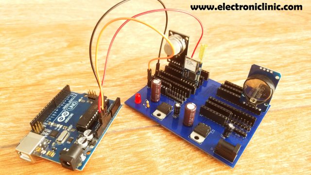
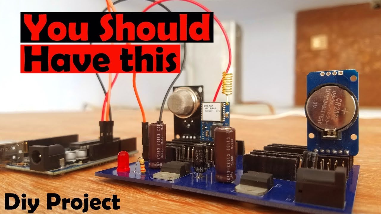
Arduino Power Supply Module for Sensors- While working on any electronics-based project you always need a power supply to power up your sensors, relays, and motors, etc. In this tutorial, you will learn how to make your own universal type Sensors power supply board.
Why you should have this Power Supply board?
How this Power Supply board can save you a lot of time?
How this Power Supply Board minimize the overall project making time?
You will get answers to all of these questions in a minute.
The PCB board used in this project is sponsored by the PCBway Company which is one of the top leading companies throughout the world. The PCB board Gerber files can be downloaded from the PCBway official website. You can find the link in the PCB layout section.
Note: Complete video tutorial is available at the end of this article.
Without any further delay let’s get started.
Amazon Links:
Disclosure: These are affiliate links. As an Amazon Associate I earn from qualifying purchases.
The most commonly used voltages are 12, 5, and 3.3 volts. The 5 volts and 3.3 volts are already available on the Arduino Uno and Mega Board. Now the question is why we need this power supply board? Well, there are some reasons for making this power supply board.
- There are situations when you need to connect multiple sensors with the Arduino or any other controller board, and you need more 5 volts, 3.3volts and ground wires. As you know in Arduino we can only connect two wires with the 5 volts and 3.3 volts. In a situation like this, we start using the breadboard, and in no time the entire board is covered with wires.
The soldering job on a Vero board becomes very hectic, there are high chances of short circuit if you are a beginner, a lot of testing and troubleshooting is required. Using this power supply board you can easily distribute the 5 volts and 3.3 volts.
- There are situations when the Arduino’s 5 volts are not enough to power up all the Sensors and electronic boards. In a situation like this, my designed Power Supply Board can be a lifesaver, you can use the regulated 5 volts from this board to power the sensors and use the Arduino’s 5 volts as well to power up some of the sensors.
Remember my Servo based project? The Arduino’s 5 volts were not enough to power up the Servo Motor, and as a result, I had to make a power supply using the Vero Board.
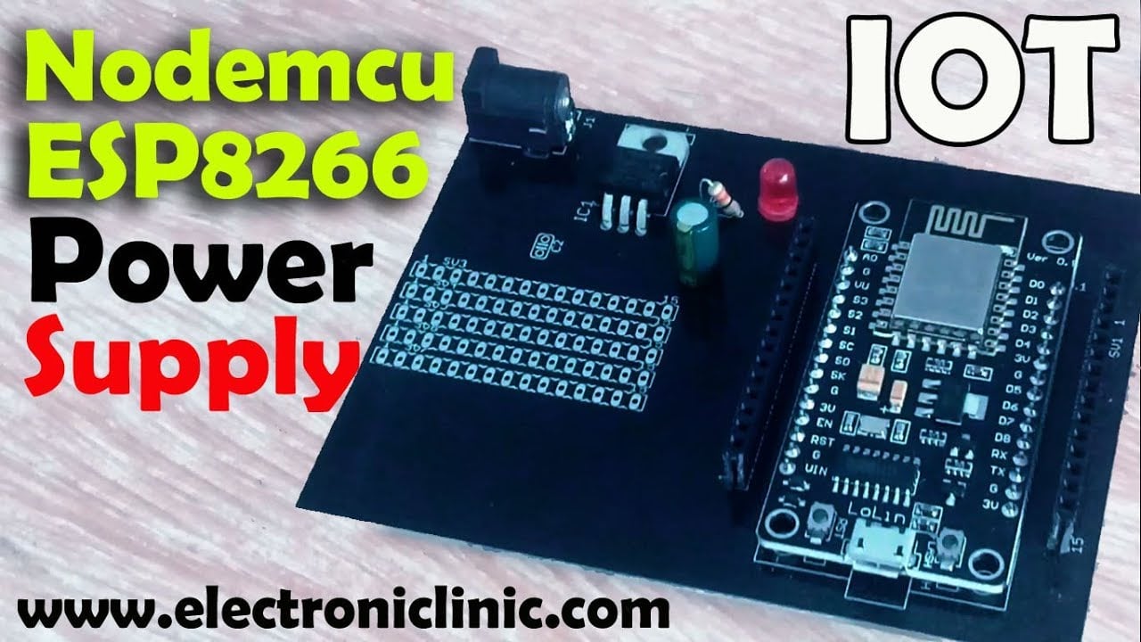
The same thing happened when I was working on the Nodemcu ESP8266 wifi module and the Arduino’s 5 volts were not enough, then I made a power supply using the Vero Board. Now using this power supply board I can easily power up the servo motor and other electronic devices without any problem.
- You know in maximum Arduino based projects relays, motors, solenoid valves, Fans, etc are used which needs 12 volts. So this board also has the 12 volts.
- Instead of using a breadboard, my designed power supply board can also be used as the development board. You can easily connect sensors with less wiring.
- In this Power Supply board the male and female headers are used, so this way you can use male to male and male to female type jumper wires.
Isn’t it amazing? It has so many advantages; I believe every Electronics lover should have this. Now I will use this Power Supply board in my upcoming projects and tutorials. Now let’s have a look at its circuit diagram.
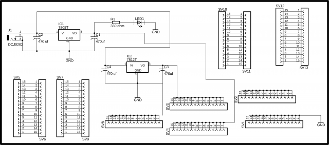
Arduino Power Supply Module Circuit Diagram:
This schematic is designed in Cadsoft Eagle 9.1.0 version. If you want to learn how to make a schematic and PCB, then watch my tutorial given below.
J1 is the female power jack and this is where we connect the Adaptor, 12v battery or a Solar Panel. This DC female Power Jack is connected with the input legs of the 7805 and 7812 voltage regulators. 470uf capacitors are connected at the input and output sides of the voltage regulators. A 330-ohm resistor is connected in series with a 2.5v LED. This is a current limiting resistor. This LED is used as the indicator, that the circuit is powered up.
From sv1 to sv12 these are the male and female headers. As you can see all the legs of the SV1 are connected together and then connected with the power supply ground. Sv2 and Sv8 are used for the 5 volts and 3.3 volts from the Arduino. Sv4 is connected with the 5v regulator. Sv3 is connected with the 12v regulator. While all the other headers are used for the Sensors. Now let’s have look at the PCB layout.
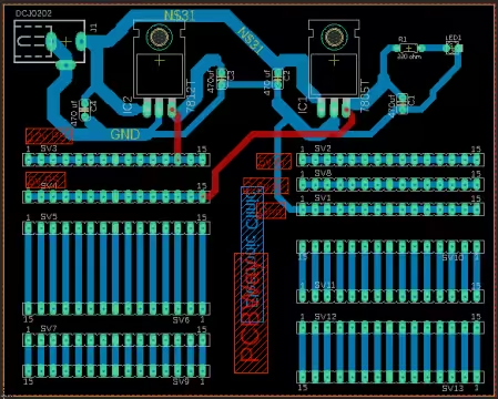
Arduino Power Supply Module PCB Layout:
Download: Arduino Power Supply Module Gerber Files
Download: Arduino Power supply Module pcb board layout file
5v from the Arduino can be connected with Sv2 and then from here, it can be connected with different sensors. Similarly, for the 3.3 volts. Ground from the Arduino can be connected with Sv1 and this is also connected with the Power Supply ground. The External Power Supply 12 volts will be available on Sv3 and 5 volts will be available on Sv4. Now it’s totally up to you, you want to use the Arduino’s 5 volts or the 5 volts from the external Power supply.
After I was done with the PCB designing then I placed an online order on the PCBway official website. I have a separate video on how to generate the Gerber files and how to place an online order the link is given in the description.
These are the PCBs manufactured by the PCBway Company, as you can see the quality is really great. Now let’s start the soldering.
Soldering:
For the Soldering watch video tutorial given at the end.
Final words about the Arduino Power Supply Module:
I wish I had designed this Arduino Power Supply Module a long time ago. After making this Power Supply Module now I can easily power up different sensors and electronic breakout boards. Now I can easily distribute the 12v, 5v, 3.3 volts, and ground wires. I think every electronics lover should have this. This Power Supply Module can really make things simple for beginners.
If you have any questions regarding this Arduino Power Supply Module designed for sensors, feel free to comment. Any suggestions will be highly appreciated. For the detailed step by step explanation watch video tutorial given below. Support my YouTube channel be Subscribing, and don’t forget to like and share this article and video.
Watch Video Tutorial:
Discover more from Electronic Clinic
Subscribe to get the latest posts sent to your email.


How can I reach you on whatsapp