Arduino16x2 i2c LCD, Nodemcu 16×2 i2c LCD Code & Library
Last Updated on May 8, 2026 by Engr. Shahzada Fahad
Table of Contents
Description:
Arduino 16×2 I2C LCD, Nodemcu 16×2 i2c LCD Code & Library- I have been using 16×2 LCD in different projects. For displaying the Date and time information, In a password-protected door security system, and so on. A regular 16×2 LCD module needs a lot of wires, due to which maximum of the controller I/O pins are wasted.
The wiring can be reduced; by replacing a regular 16×2 LCD with the I2C supported 16×2 LCD. The i2c 16×2 LCD is in fact the same LCD but it comes with the i2c driver module soldered on the backside of the LCD;
This type of the LCD can be interfaced with any controller board using only 2 wires.
In this tutorial, you will learn how to display text on the i2c 16×2 LCD using Arduino. In this tutorial you will also learn how the same i2c 16×2 LCD can be interfaced with the Nodemcu ESP8266 Wifi Module which used in IOT based projects.
Without any further delay let’s get started!!!
Amazon Purchase links :
Arduino Nano USB-C Type (Recommended)
*Disclosure: These are affiliate links. As an Amazon Associate I earn from qualifying purchases.
About the i2c 16X2 LCD and Pinout:
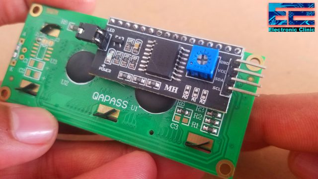
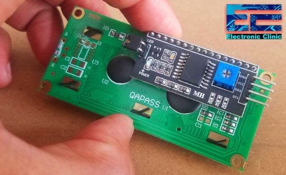
This is just a normal 16×2 LCD which is converted into an i2c supported type LCD by using the PCF8574 i2c Driver module. The four male headers are clearly labeled as GND, VCC, SDA, and SCL. A 10K variable resistor which is used for the adjustment of the LCD contrast.
I2c addresses:
As you can see the driver module is also provided with A0, A1, and A2 links which can be used to set the i2c address. As you can see no links are fitted the 7-bit address is 0x27 which you have to confirm in the datasheet, may be your LCD have a different i2c address. The links control the least significant 3 bits, fitting the link sets the bit low.
Arduino 16×2 LCD i2c Circuit Diagram:
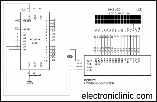
As you can see the circuit diagram is really simple. All the 16 pins of the PCF8574 driver module are connected with the LCD pins. Using these connections you can convert any 16×2 LCD into an i2c supported LCD. The VCC pin is connected with the Arduino’s 5 volts, the SDA pin is connected with the Arduino’s Analog pin A4, the SCL pin is connected with the Arduino’s Analog pin A5, while the GND pin is connected with the Arduino’s ground. Using only two pins A4 and A5 we can control the 16×2 LCD.
16×2 i2c LCD interfacing with Arduino:
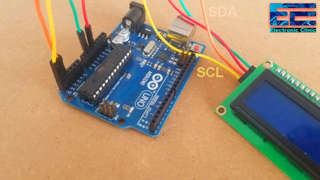
The 4 pins of the i2c LCD driver module are connected as per the circuit diagram. The VCC and GND pins are connected with the Arduino 5 volts and ground, while the SDA and SCL pins are connected with the Arduino’s Analog pins A4 and A5. Now, let’s have a look at the Arduino programming.
Arduino 16×2 LCD i2c Code/Programming:
|
1 2 3 4 5 6 7 8 9 10 11 12 13 14 15 16 17 18 19 20 21 22 23 24 25 26 27 28 29 30 31 32 33 34 35 36 37 38 39 40 |
//libraries download links are given below. #include <Wire.h> #include <LiquidCrystal_I2C.h> LiquidCrystal_I2C lcd(0x27,16,2); //0x27 is the i2c address, while 16 = columns, and 2 = rows. void setup() { lcd.init(); //Init the LCD lcd.backlight(); //Activate backlight lcd.home(); } void loop() { lcd.clear(); lcd.print("electroniClinic"); delay(1000); lcd.setCursor(0,1); for (int i=0; i<=5; i++) //the columns are automatically incremented { lcd.print(i); delay(500); } lcd.clear(); lcd.setCursor(0,0); lcd.print("electroniClinic"); for (int i=0; i<=5; i++) { lcd.setCursor(0,1); lcd.print(i); delay(500); } lcd.noDisplay(); delay(500); // Turn on the display: lcd.display(); delay(500); } |
I2C LCD Arduino program explanation:
Before you start the programming, first of all, make sure you download the wire and LiquidCrystal_I2C libraries by clicking on the download links given below.
Download Wire library: Wire
Download LiquidCrystal_I2C Library: LiquidCrystal_I2C
#include <Wire.h>
#include <LiquidCrystal_I2C.h>
LiquidCrystal_I2C lcd(0x27,16,2); //0x27 is the i2c address, while 16 = columns, and 2 = rows.
The 0x27 is the i2c address if your LCD doesn’t work change this address which you can find in the datasheet. The values 16 and 2 means, that I am using a 16×2 LCD. If you are using a 16×4 LCD then simply replace 2 with 4, and similarly for the other same series LCDs.
void setup() {
lcd.init(); //Init the LCD
lcd.backlight(); //Activate backlight
lcd.home();
}
In the void setup() function we simply initialize the lcd. Activate the LCD backlight. And Finally, we set the cursor at the top left corner of the 16×2 LCD. You can also use the lcd.setCursor() function. Even if you don’t use this function it’s ok, the default location is already the first row and first column.
Then starts the void loop function.
void loop() {
lcd.clear();
The lcd.clear() function is used to clear the LCD.
lcd.print(“electroniClinic”);
delay(1000);
The lcd.print() function is used for writing anything on the LCD. Then there is a delay of 1 second.
As you know the LCD I am using is a 16×2 LCD which means it has 16 columns and 2 rows. Using the lcd.setCursor function you can select any of the two rows and any column. 0 and 1 means, the first column of the second row.
The purpose of this for loop is to print numbers from 0 to 5 with a delay of 500 milliseconds, the columns are automatically incremented.
lcd.setCursor(0,1);
for (int i=0; i<=5; i++) //the columns are automatically incremented
{
lcd.print(i);
delay(500);
}
lcd.clear();
lcd.setCursor(0,0);
lcd.print(“electroniClinic”);
for (int i=0; i<=5; i++)
{
lcd.setCursor(0,1);
lcd.print(i);
delay(500);
}
Again I cleared the lcd, selected the first column and first row, printed electroniclinic. And then the same for loop but this time I have used the lcd.setCursor() function. which keeps the cursor at 1 column and 2nd row.
lcd.noDisplay();
delay(500);
// Turn on the display:
lcd.display();
delay(500);
To turn off the display you can use the lcd.noDisplay() function and to turn on the display you can use the lcd.display() function.
}
For the practical demonstration watch video given at the end of this article.
Now I am going to explain how you can interface the same LCD with the Nodemcu ESP8266 wifi module which is quite popular for making IOT based projects.
About the Utsource.net:
Utsource.net has a wide range of IC chips, passive electronic components, Fiber optics, controller boards, Sensors, protection modules, LEDs, electromechanical relays, accessories, and tools. Start now by creating a new account and get a 5 dollars shipping coupon.
It is a trustworthy website for ordering electronic components to complete projects, free shipping can be provided on selected order for a 2-5 days delivery.

I2C 16×2 LCD with Nodemcu ESP8266 Circuit Diagram:

The 16×2 LCD connection with the PCF8574 I2C driver remains the same. This time the SCL and SDA pins of the I2C LCD converter are connected with the Nodemcu digital pins D3 and D4. A regulated power supply based on the LM7805 voltage regulator is used to power up the Nodemcu ESP8266 Wifi module and 16×2 I2C supported LCD. Now let’s have a look at the Nodemcu programming.
LCD 16×2 I2C Nodemcu programming:
|
1 2 3 4 5 6 7 8 9 10 11 12 13 14 15 16 17 18 19 20 21 22 23 24 25 26 27 28 29 30 31 32 33 34 35 36 37 38 39 40 |
#include <Wire.h> #include <LiquidCrystal_I2C.h> LiquidCrystal_I2C lcd(0x27,16,2); //0x27 is the i2c address, while 16 = columns, and 2 = rows. void setup() { Wire.begin(2,0); // gpio 2 and gpio 0 which are D4, and D3 lcd.init(); //Init the LCD lcd.backlight(); //Activate backlight lcd.home(); } void loop() { lcd.clear(); lcd.print("electroniClinic"); delay(1000); lcd.setCursor(0,1); for (int i=0; i<=5; i++) //the columns are automatically incremented { lcd.print(i); delay(500); } lcd.clear(); lcd.setCursor(0,0); lcd.print("electroniClinic"); for (int i=0; i<=5; i++) { lcd.setCursor(0,1); lcd.print(i); delay(500); } lcd.noDisplay(); delay(500); // Turn on the display: lcd.display(); delay(500); } |
This is exactly the same program with a little modification, this time in the void setup function I used the wire.begin() function. 2 and 0 are the gpio 2 and gpio 0 pins on the nodemcu module which are actually the D4 and D3 pins.
The rest of the program is exactly the same, which I have already explained.
Watch Video Tutorial:
Related Article:
16×2 LCD basic examples
Discover more from Electronic Clinic
Subscribe to get the latest posts sent to your email.


