Countdown timer using Arduino, LCD 16×2 i2c & 4×3 Keypad
Last Updated on May 8, 2026 by Engr. Shahzada Fahad
Table of Contents
Description:
Countdown timer using Arduino- in this tutorial, you will learn how to make an advanced level Countdown timer based on the Arduino, 16×2 i2c LCD, and a 4×3 keypad. This countdown timer is entirely different from the rest of the countdown timers available on the internet. This countdown timer can be used as the end product. With the help of this Countdown timer, you can control different types of electrical loads like for example Light Bulbs, Heaters, Water Pumps, Washing Machines, Fans, etc. in fact, this countdown timer can be used anywhere where you need to control anything on the time basis. This countdown timer is ideal for AC and DC loads.
Before, I am going to explain the circuit diagram of the Arduino-based countdown timer, Simulation, and programming; first I am going to explain how this project actually works.
Using this Arduino-based countdown timer is very simple; the instructions are displayed on the 16×2 LCD. The user simply enter the time in minutes and seconds and press the Asterisks “*” key on the Keypad. The total time is displayed in seconds. The timer is started which is based on the millis function. The load which is connected with the relay is turned ON. This load will remain ON until the total seconds’ decrements to 0.
If at any time you need to change the minutes and seconds, you can simply press the Hash “#” key on the keypad which will take you back to the main screen, and you can start again by entering the minutes and seconds.
Without any further delay let’s get started!!!
Note: for practical demonstration and complete project explanation watch video given at the end of this article.
Amazon Purchase Links:
Arduino Nano USB-C Type (Recommended)
Other Tools and Components:
ESP32 WiFi + Bluetooth Module (Recommended)
Super Starter kit for Beginners
PCB small portable drill machines
*Please Note: These are affiliate links. I may make a commission if you buy the components through these links. I would appreciate your support in this way!
What is a timer and its types:
A timer is a specially designed clock that is used for measuring specific timer intervals. Timers can be divided into two main types. A timer which is capable of counting time intervals upwards from zero for measuring the elapsed time is usually called a stopwatch, while on the other hand a device or a clock which counts down from a specified time interval is more usually called a timer, which is also known as the countdown timer.
About the 4×3 keypad:

This is the 4×3 keypad, 4×3 means that this keypad has 4 rows and 3 columns. The first contact is the C1, 2nd one is the R0, 3rd contact is the C0, 4th contact is the R3, 5th contact is the C2, 6th contact is the R2, and 7th contact is the R1.
You can also use a 4×4 keypad; leave the 4th column c4 unconnected. As you can see the 4×3 keypad has no headers and wires, due to which it can’t be interfaced with the Arduino.

I interfaced female headers with the 4×3 keypad, now it can be easily interfaced with the Arduino board.
About the i2c 16×2 LCD:
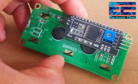
This is just a normal 16×2 LCD which is converted into an i2c supported type LCD by using the PCF8574 i2c Driver module. The four male headers are clearly labeled as GND, VCC, SDA, and SCL. A 10K variable resistor which is used for the adjustment of the LCD contrast.
I2c addresses:

As you can see the driver module is also provided with A0, A1, and A2 links which can be used to set the i2c address. As you can see no links are fitted the 7-bit address is 0x27 which you have to confirm in the datasheet, may be your LCD have a different i2c address. The links control the least significant 3 bits, fitting the link sets the bit low.
Countdown Timer Circuit Diagram:

As you can see the circuit diagram is really simple. All the 16 pins of the PCF8574 driver module are connected with the LCD pins. Using these connections you can convert any 16×2 LCD into an i2c supported LCD. The VCC pin is connected with the Arduino’s 5 volts, the SDA pin is connected with the Arduino’s Analog pin A4, the SCL pin is connected with the Arduino’s Analog pin A5, while the GND pin is connected with the Arduino’s ground. Using only two pins A4 and A5 we can control the 16×2 LCD. You don’t need to purchase the 16×2 LCD and the PCF8574 driver module separately, you can purchase a readymade module, the purchase link is given above.
A 4×3 keypad is interfaced with the Arduino using the digital pins 4, 5, 6, 7, 8, 9, and 10. The 4×3 keypad rows are connected with 4, 5, 6, and 7. While the 4×3 keypad columns are connected with 8, 9, and 10. You can also use a 4×4 keypad leaving column 4 of the 4×4 keypad unconnected.
A one channel relay module is connected with the digital pin 13 of the Arduino. The relay used is of the type SPDT “Single Pole and Double Throw”. You can purchase a readymade relay module or you can follow the same exact connections and build the one by yourself.
Countdown Timer Proteus Simulation:
Before the actual wiring, I designed a simulation of the countdown timer in Proteus, which really helped me in completing my programming without physically connecting the Arduino and other components. Proteus is really powerful simulation software, especially for beginners. If you don’t have the components you can install a free version of the Proteus simulation software and make the simulation by yourself or you can download the simulation of the countdown timer given below.
Download Countdown Timer Proteus Simulation

I connected everything as per the circuit diagram which I already explained in very detail. In the simulation, you can see I have not connected the 10k resistor at the base of 2n2222, but in practical you must connect this resistor. So, after completing the connections the next step was to start the programming using the Arduino IDE.
Countdown Timer Arduino Code / Programming:
|
1 2 3 4 5 6 7 8 9 10 11 12 13 14 15 16 17 18 19 20 21 22 23 24 25 26 27 28 29 30 31 32 33 34 35 36 37 38 39 40 41 42 43 44 45 46 47 48 49 50 51 52 53 54 55 56 57 58 59 60 61 62 63 64 65 66 67 68 69 70 71 72 73 74 75 76 77 78 79 80 81 82 83 84 85 86 87 88 89 90 91 92 93 94 95 96 97 98 99 100 101 102 103 104 105 106 107 108 109 110 111 112 113 114 115 116 117 118 119 120 121 122 123 124 125 126 127 128 129 130 131 132 133 134 135 136 137 138 139 140 141 142 143 144 145 146 147 148 149 150 151 152 153 154 155 156 157 158 159 160 161 162 163 164 165 166 167 168 169 170 171 172 173 174 175 176 177 178 179 180 181 182 183 184 185 186 187 188 189 190 191 192 193 194 195 196 197 198 199 200 201 202 203 204 205 206 207 208 209 210 211 212 213 214 215 216 217 218 219 220 221 222 223 224 225 226 227 228 229 230 231 232 233 234 235 236 237 238 239 240 241 242 243 244 245 246 247 248 249 250 251 252 253 254 255 256 257 258 259 260 261 262 263 264 265 266 267 268 269 270 271 272 273 274 275 276 277 278 279 280 281 282 283 284 285 286 287 288 289 290 291 292 293 294 295 296 297 298 299 300 301 302 303 304 305 306 307 308 309 310 311 312 313 314 315 316 317 318 319 320 321 322 323 324 325 326 327 328 329 330 331 332 333 334 335 336 337 338 339 340 341 342 343 344 345 346 347 348 349 350 351 352 353 354 355 356 357 358 359 360 361 362 |
#include <Keypad.h> //#include <LiquidCrystal.h> #include <Wire.h> #include <LiquidCrystal_I2C.h> LiquidCrystal_I2C lcd(0x27,16,2); //0x27 is the i2c address, while 16 = columns, and 2 = rows. #include<stdio.h> const byte ROWS = 4; //four rows const byte COLS = 3; //three columns char keys[ROWS][COLS] = { {'1','2','3'}, {'4','5','6'}, {'7','8','9'}, {'*','0','#'} }; byte rowPins[ROWS] = {4, 5, 6, 7}; //connect to the row pinouts of the keypad byte colPins[COLS] = {8, 9, 10}; //connect to the column pinouts of the keypad Keypad keypad = Keypad( makeKeymap(keys), rowPins, colPins, ROWS, COLS ); int relay = 13; int counter = 0; int attempts = 0; int max_attempts = 3; String mymints; int minutes = 0; String mysecs; int seconds = 0; long int total_seconds = 0; int secflag = 0; int timer_started_flag = 0; // Tracks the time since last event fired unsigned long previousMillis=0; unsigned long int previoussecs = 0; unsigned long int currentsecs = 0; unsigned long currentMillis = 0; int interval= 1 ; // updated every 1 second int tsecs = 0; void setup(){ Serial.begin(9600); lcd.init(); //Init the LCD lcd.backlight(); //Activate backlight pinMode(relay, OUTPUT); digitalWrite(relay, LOW); Serial.println("enter password"); lcd.print("Countdown Timer"); delay(2000); lcd.clear(); lcd.print("Enter Minutes:"); } void loop() { keypadfunction(); } void keypadfunction() { char key = keypad.getKey(); if (key){ Serial.println(key); counter = counter + 1; lcd.setCursor(counter, 1); lcd.print(key); } if (key == '1') { mymints = mymints + 1; } if (key == '2') { mymints = mymints + 2; } if (key == '3') { mymints = mymints + 3; } if (key == '4') { mymints = mymints + 4; } if (key == '5') { mymints = mymints + 5; } if (key == '6') { mymints = mymints + 6; } if (key == '7') { mymints = mymints + 7; } if (key == '8') { mymints = mymints + 8; } if (key == '9') { mymints = mymints + 9; } if (key == '0') { mymints = mymints + 0; } if (key == '#') { counter = 0; mymints = ""; minutes = 0; mysecs = ""; seconds = 0; secflag = 0; lcd.clear(); lcd.setCursor(0,0); lcd.print("Enter Minutes:"); } if (key == '*') { lcd.clear(); minutes = mymints.toInt(); Serial.println(minutes); lcd.clear(); lcd.print("Minutes: "); lcd.setCursor(0,1); lcd.print(minutes); mymints = ""; // empty the string delay(2000); lcd.clear(); lcd.setCursor(0,0); lcd.print("Enter Seconds:"); counter = 0; secflag = 1; while(secflag == 1) { forSeconds(); } } } void forSeconds() { char key = keypad.getKey(); if (key){ Serial.println(key); counter = counter + 1; lcd.setCursor(counter, 1); lcd.print(key); } if (key == '1') { mysecs = mysecs + 1; } if (key == '2') { mysecs = mysecs + 2; } if (key == '3') { mysecs = mysecs + 3; } if (key == '4') { mysecs = mysecs + 4; } if (key == '5') { mysecs = mysecs + 5; } if (key == '6') { mysecs = mysecs + 6; } if (key == '7') { mysecs = mysecs + 7; } if (key == '8') { mysecs = mysecs + 8; } if (key == '9') { mysecs = mysecs + 9; } if (key == '0') { mysecs = mysecs + 0; } if (key == '#') { counter = 0; mymints = ""; minutes = 0; mysecs = ""; seconds = 0; secflag = 0; lcd.clear(); lcd.setCursor(0,0); lcd.print("Enter Minutes:"); } if (key == '*') { lcd.clear(); seconds = mysecs.toInt(); Serial.println(seconds); lcd.clear(); lcd.setCursor(0,0); lcd.print("Seconds: "); lcd.setCursor(0,1); lcd.print(seconds); mysecs = ""; // empty the string delay(2000); lcd.clear(); lcd.setCursor(0,0); lcd.print("Mins Secs"); lcd.setCursor(1,1); lcd.print(minutes); lcd.setCursor(10,1); lcd.print(seconds); total_seconds = (minutes * 60) + seconds ; counter = 0; secflag = 0; timer_started_flag = 1; lcd.clear(); lcd.print("T Seconds:"); lcd.setCursor(11,0); lcd.print( total_seconds ); delay(3000); while( timer_started_flag == 1) { char key = keypad.getKey(); if (key){ Serial.println(key); counter = counter + 1; lcd.setCursor(counter, 1); } if (key == '#') { counter = 0; mymints = ""; minutes = 0; mysecs = ""; seconds = 0; secflag = 0; total_seconds = 0; timer_started_flag = 0; lcd.clear(); lcd.setCursor(0,0); lcd.print("Enter Minutes:"); } // lcd.clear(); lcd.setCursor(0,0); lcd.print("T Seconds:"); lcd.setCursor(11,0); lcd.print( total_seconds ); lcd.setCursor(0,1); if( total_seconds > 0) { digitalWrite(relay, HIGH); lcd.print("load ON "); } if( total_seconds <= 0) { total_seconds = 0; digitalWrite(relay, LOW); lcd.print("load OFF"); } currentMillis = millis(); currentsecs = currentMillis / 1000; if ((unsigned long)(currentsecs - previoussecs) >= interval) { total_seconds = total_seconds - 1; lcd.clear(); previoussecs = currentsecs; } } } } |
Countdown timer Arduino code explanation:
Before you start the programming, first of all, make sure you download the wire and LiquidCrystal_I2C libraries by clicking on the link given below:
Maximum of the code used in the project, I have already explained in my previous tutorial which was based on the Password Door Lock Security System using Arduino and Keypad. So, if you find the programming a bit complex you can read the above article.
The new things that I added in this project are the 16×2 i2c LCD and the millis() function. for counting the seconds I used the millis() function. So this countdown timer is actually based on the millis() function.
Running the Countdown Timer simulation:
Once, I was done with the programming, I simply compiled the program and generated the Hex file link. If you are not able to see the Hex file link then flow the steps given below.
Click on the File Menu and select preferences.

This will open the preference window. Make sure you check the compilation and upload boxes and then click on the Ok button.

Now to generate the Hex file simply click on the Verify button, and wait for a while. Once the program is compiled then you can copy the Hex link.

I selected the entire link, pressed ctrl + c on the keyboard to copy the link and then pasted this link into the Arduino Uno board in the Proteus simulation software.
While the countdown timer simulation is opened, double click on the Arduino Uno and paste the copied link into the program file text field.

That’s it.
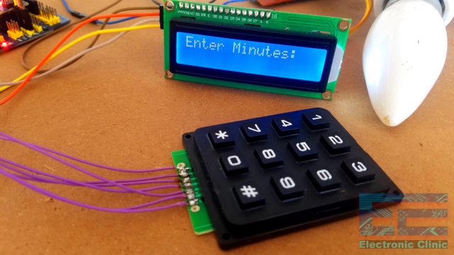
To run the simulation I clicked on the play button. Initially, there were some logical errors, so after 2 hours of programming, I fixed everything. Each time I was doing any change in the Arduino programming, I was compiling the program to update the Hex file. Finally, everything worked the way I wanted. The following are the screenshots of the project in action. Initially when you run the simulation. You will be asked to enter the minutes.


I entered 1 minute using the keypad and pressed the Asterisks key on the keypad to complete my entry, you can add more minutes but make sure you press the Asterisks key at the end. After entering the minutes then I was asked to enter the seconds.

I entered 2 seconds and pressed the Asterisks key on the keypad. So the total entered time is 1 minute and 2 seconds. the minutes were converted into seconds. so on the LCD, the total time will be displayed in seconds which is 62 minutes. Initially, you can see the Load is OFF. So after entering the seconds and pressing the Asterisks key the timer started after 2 seconds and also turned ON the Load connected with the relay.

The timer started it turned ON the load, as you can see on the LCD, the total seconds remaining and the load status which shows that currently, the load is ON. Once the time was completed i.e the total seconds decremented to zero. The load status on the LCD change from load ON to load OFF and also the relay was turned OFF.

To start again, you can press on the Hash “#” key, and you can start again by entering the minutes and seconds. I checked it so many times and there were no bugs and malfunction. At this point, I was satisfied with all the connections and programming, and now I was ready for the practical connections.
Countdown Timer Final Look:
This is how the Countdown Timer looks after the final connections. All the components are interfaced as per the circuit diagram. It will look amazing if all the components are packed inside an enclosure. You can make the one using a 3d printer. Or purchase the readymade plastic enclosure.
The final step was to power up the Arduino, and one channel relay module using the 12 volts. I checked this project so many times and it worked perfectly. For the practical demonstration watch video tutorial given below.

Watch Video Tutorial:
Related Article:
16×2 LCD basic examples
Discover more from Electronic Clinic
Subscribe to get the latest posts sent to your email.


thanks for the project. i need to modify the the code. i must input seconds only, than a servo must do a sweep on the program must loop for the time input rotating the servo though an angle , then wait the input time and do it again till a button is press to reset and input a new time. i you can help i would really be very thank full as i need this to complete my enealing machine. the events will be input time, servo 1 does a sweep, timer swithes on the oscillator via relay, vervo does a sweep and then resets to start again with the time input.
when i run the coding, this appear “Keypad.h: No such file or directory”
how im going to solve this problem ????
this is just because of the library. I have shared a link from where you can download the libraries.
Please … how can I add buzzer to the timer?
in code it shows an error message
can you make another one, but with an esp32?
if so, can you link it too?
https://www.circuitbasics.com/how-to-set-up-a-keypad-on-an-arduino/ I found this page before changing my personal sketch to match the parameters of your code. The main difference is the Columns and Rows definitions were different for my personal 3×4 number-pad matrix, despite it looking like yours shown. for help to other experimenters please note where the code says:
byte rowPins[ROWS] = {….. and
byte colPins[COLS] = {…..
the following corrected my initial issues:
byte rowPins[ROWS] = {7, 2, 3, 5};
byte colPins[COLS] = {6, 8, 4};
I found out later that this was mainly due to my pin assignment missing the inital first pin and last pin. I was supposed to have numbered the pins from first to last 1,2,3,4,5,6,7,8,9,10 connecting to Pin Arduino Uno r3 Digital Pins following the standard TX and RX Board Pins. 3,4,5,6,7,8,9,10,11. This explained the outcome shown….. at least I think so.
Just One thing, How do I enable “Line” numbering within the main Arduino IDE?
In the end I should at least be experienced to use Proteus for a project in the near future. I have since Subscribed to the suitable YouTube Channel. A big thanks to you all.
Dear Engr,
I am new on ardiuno and do know many things about it. Thank you for your sharing the codes.
I have a quick question. The codes you shared is very useful for me, but all I need is similar codes for miliseconds and seconds couple (not seconds and minutes couple as you shared). I tried to change the codes for the one I need, but I could not do that.
Could you kindly please share the codes for me ?
Hi
I want to make a led flasher with keypad lcd to learnig , set on off flasher bettwen a time set
But i onlly can show nomber keypad on lcd
hello
i am studiing your Countdown timer using Arduino, LCD 16×2 i2c & 4×3 Keypad webpage
my single question : is there a limit to the minutes input ex “200”
many thanks
mik
You link to solid state relays but do not say what voltage the relay is running at. I assume 5 volts but not positive. What should the spec on the relay be other than Spst?
Thank you.
Your BOM (Bill of Materials) lists both the Uno and the Nano but the text and drawings only show the Uno. Are any of the pins different for the Nano so that either a Uno or Nano can be plugged into the female headers (you did use plug in headers didn’t you)? Are there any changes in code needed if a Nano is used instead of the Uno?
If an optoisolator is used where does it hook in and how? I assume if an SSR (solid state relay) is used that an external power supply would be needed for the Uno/Nano and relay or at least the relay. Is that correct?
Thank you.