Deaf People Arduino Wireless Project using NRF24L01 modules and Micro Vibration Motor
Table of Contents
Deaf People Arduino Wireless Project:
Deaf People Arduino Wireless Project- Living with a deaf person at times can be really challenging, as the person you are trying to communicate with is not able to hear anything you say. You stand at the door for minutes, you keep on knocking the door and no matter how many times you ring the bell, you get no response at all. The same thing happens when a baby is crying, or you are in the room and you need help. A housewife or any other person with no sense of hearing will face these very common issues. In this tutorial, I will make a prototype model that can be used to let the deaf person know that we need her/him. So, before I am going to explain the working, making, and programming, first a few words about the sponsor of this project for sending me these quality PCBs.
About the Sponsor, ALLPCB:
ALLPCB is the World’s Fastest PCB Manufacturing Company. Feel free to visit their website allpcb.com to not only find out what awesome PCB and assembly services they offer but also to easily upload your Gerber files and thus order affordable and High-quality PCBs quickly. Besides this, you will also get a 30 Dollars Coupon balance, which you can use to get your first prototype order for free.
In this article, you will learn how to make a long-range wireless notifier system for deaf people using Arduino, NRF24L01 Transceiver modules, and a Micro Vibration Motor. A pushbutton is connected with the Transmitter side and a Micro Vibration Motor is connected with the Receiver side. All you need is to press the push button and the vibration motor will start on the receiver side. You can set the vibration intensity in the programming. You can make this project more advance by using multiple transmitters, this way you can install one transmitter at the door, one transmitter with the baby and you can add a sound sensor, so when the baby is crying the deaf person will know, and so on. I have already explained in my previous tutorial how to add multiple transmitters with a single receiver. You should read this article if you want to learn how to use multiple NRF24L01 modules.
These are the same PCBs I used in the Long range wireless battery voltage monitoring system using an android cell phone application. I have already explained the PCB designing and soldering. So, I highly recommend watch my tutorial on the long-range wireless battery voltage monitoring system, if you want to learn how to make these NRF24L01 and Arduino based development boards. I didn’t make any changes to the PCBs, I only added a pushbutton on the transmitter side and the micro-vibration motor on the receiver side. So, anyhow this is just a prototype model, the size can be reduced, we don’t need this area on the left and right side consisting of holes and extra headers, the NRF24L01 module, and the micro-vibration motor can be fixed underneath the Arduino Nano.
I designed these parts in Solidworks 2016 with the same exact dimensions to check if these modules will really fit underneath the Arduino board. Now all you need is to design a plastic enclosure for this and then you can wear it like a watch. The size can be further reduced by using the Arduino Pro Mini. So, this way you can make a small wearable device, and then you can power up all the electronics using the small Lipo battery. You can make this a smart deaf people project by adding an Oled display module at the top this way you can also display text on the display module. I am sure you have got an idea of what you are going to learn after watching this video.
Without any further delay, let’s get started!!!
Amazon Purchase Links:
Arduino Nano USB-C Type (Recommended)
Other Tools and Components:
ESP32 WiFi + Bluetooth Module (Recommended)
Super Starter kit for Beginners
PCB small portable drill machines
*Please Note: These are affiliate links. I may make a commission if you buy the components through these links. I would appreciate your support in this way!
Micro Vibration Motor:
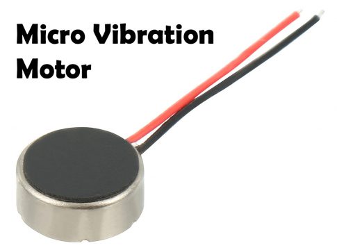
This is the DC 3V 12000rpm Flat Coin Button-Type Micro DC Vibrating Motor. This Micro Vibration Motor is widely used in mobile phones, RFID scanners, toys, health care products, electronic products, medical equipments or Industrial tools etc.
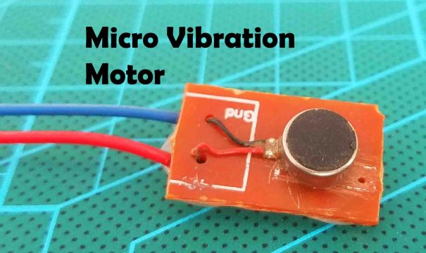
For the easy use and to avoid any damage I fixed it on this small PCB board. This micro vibration motor has two wires the Red and Black. Red is the positive and of course black is the GND. Now, let’s take a look at the transmitter and receiver side circuit diagrams.
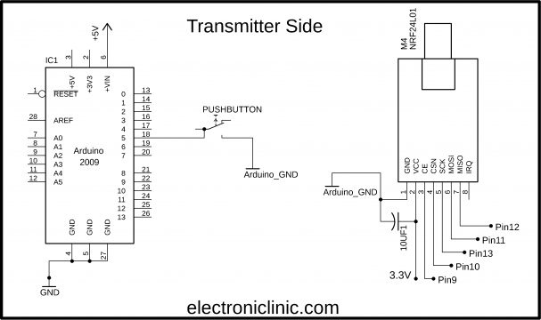
Deaf People Arduino Wireless, Transmitter Circuit Diagram:
This is the transmitter side circuit diagram. The VCC and GND pins of the NRF24L01 module are connected with the Arduino’s 3.3V and GND pins. A decoupling capacitor of 10uF is also connected between the VCC and GND pins. CE pin is connected with Pin9, CSN is connected with the Pin10, SCK is connected with pin13, MOSI pin is connected with Pin11, and the MISO pin of the NRF24L01 Transceiver module is connected with the Arduino’s Pin12.
A push button is connected with the Arduino’s pin 5.
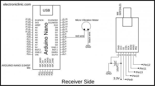
Deaf People Arduino Wireless, Receiver Circuit Diagram:
This is the Receiver side circuit diagram. The NRF24L01 Transceiver module connection with the Arduino remains exactly the same. The Red wire of the Micro vibration motor is connected with the Arduino’s PWM pin 5 and the Black wire is connected with the Arduino’s ground.
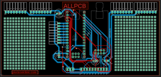
NRF24L01 Development Board PCB Design:
I designed a development board for the NRF24L01, which I can use with both the transmitter and receiver sides. I added these extra holes on the left and right sides for soldering other electronic components. I also added female headers for the 5V, GND, Analog and other I/O pins. This way I can easily interface other input and output devices. I double-checked all the connections and once satisfied; I generated the Gerber files and placed an online order on the ALLPCB official website.
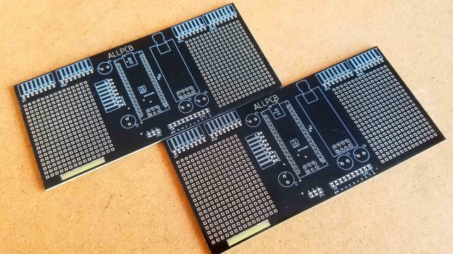
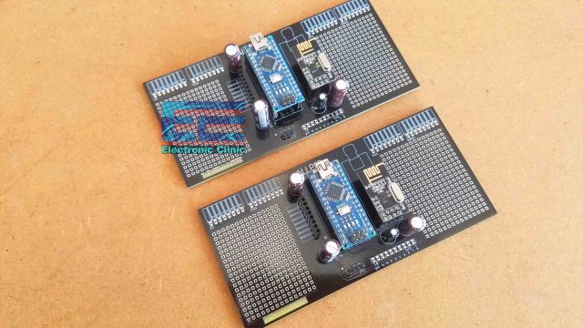
These are the PCBs I received from the ALLPCB Company. As you can see the Quality is really great, the silkscreen is quite clear, and the black color soldermask looks amazing. Next I started off by placing the components and completed the soldering job.
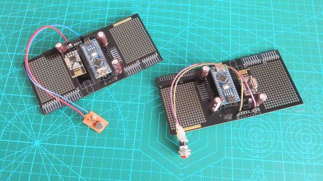
Both the circuits are exactly the same, at this point you have to decide which one you want to use as the transmitter and which one you want to use as the receiver.
Micro Vibration Motor and NRF24L01 Interfacing with Arduino:
I connected the Micro Vibration Motor and the Pushbutton as per the circuit diagram already explained; now let’s take a look at the Transmitter and Receiver side programming.
Deaf People Arduino Wireless Project Programming:
This project is based on two programs. One program is written for the Transmitter side while the other program is written for the Receiver side. Before you start the programming first of all, make sure you download all the necessary libraries. You will also need to download the RF24Network Library and the RF24 library.
These are the same programs which I used in the multiple transmitters and single receiver project, I did a few changes which I am going to explain. So, first let’s start with the Transmitter side programming.
Deaf People Arduino Wireless Project, Transmitter Code:
|
1 2 3 4 5 6 7 8 9 10 11 12 13 14 15 16 17 18 19 20 21 22 23 24 25 26 27 28 29 30 |
// Node01 #include <RF24.h> #include <RF24Network.h> #include <SPI.h> RF24 radio(9, 10); // nRF24L01 (CE,CSN) RF24Network network(radio); // Include the radio in the network const uint16_t this_node = 01; // Address of this node in Octal format const uint16_t node00 = 00; unsigned long data[6]; // number of sensors or values to send int Pushbutton = 5; // Push Button is connected with the Arduino's pin 5 int bstate = 0; // this stores the button state in the form of 0 or 1 void setup() { SPI.begin(); radio.begin(); network.begin(90, this_node); //(channel, node address) radio.setDataRate(RF24_2MBPS); pinMode(Pushbutton, INPUT_PULLUP); } void loop() { network.update(); unsigned long bstate = digitalRead(Pushbutton); // reads the button state data[0] = bstate; // stores the button state at location 0 in the array RF24NetworkHeader header7(node00); bool ok = network.write(header7, &data, sizeof(data)); // Send the data } |
Code Explanation:
This time I added these two lines
int Pushbutton = 5;
int bstate = 0;
For the pushbutton. In the void setup function I set the pushbutton as the input. In the void loop function we read the digital state of the Arduino’s pin 5 and store it in the bstate variable which is then stored in the data array at location 0 and finally we send the data array to the node00 which is the receiver side. Now, let’s take a look at the receiver side programming.
Deaf People Arduino Wireless Project, Receiver Code:
|
1 2 3 4 5 6 7 8 9 10 11 12 13 14 15 16 17 18 19 20 21 22 23 24 25 26 27 28 29 30 31 32 33 34 35 36 37 38 39 40 41 42 43 44 45 46 47 48 49 50 51 |
// Node00 #include <RF24.h> #include <RF24Network.h> #include <SPI.h> #include <Wire.h> RF24 radio(9, 10); // nRF24L01 (CE,CSN) RF24Network network(radio); // Include the radio in the network const uint16_t this_node = 00; // Address of our node in Octal format unsigned long data[6]; // number of sensors unsigned long data1; int VibrationMotor = 5; void setup() { Serial.begin(9600); SPI.begin(); radio.begin(); network.begin(90, this_node); //(channel, node address) radio.setDataRate(RF24_2MBPS); pinMode(VibrationMotor, OUTPUT); } void loop() { network.update(); while ( network.available() ) { // Is there any incoming data? RF24NetworkHeader header; network.read(header, &data, sizeof(data)); // Read the incoming data if (header.from_node == 1) { // If data comes from Node 01 data1 = data[0]; if( data1 == 1) { analogWrite(VibrationMotor, 0); } if( data1 == 0) { analogWrite(VibrationMotor, 200); // change this value if you need more or less vibration } } } } |
Code Explanation:
On the receiver side I deleted the libraries which I added for the i2c LCD. I defined a pin for the micro vibration motor. I selected pin 5 of the Arduino which is the PWM pin. The reason I am using a PWM pin is to control the vibration intensity. In the void setup function I set the Vibration motor as output.
Finally, we check if we have received the data from the node01. So, if the data is received then store the value in data1. Then we use the two if conditions to check if the received number is 1 or 0. If the received number is 1 then stop the vibration motor and if the received number is 0 then it means the pushbutton on the transmitter side is pressed, so the Arduino starts the vibration motor, 200 represents the vibration intensity. You can set any value between 0 and 255. So, that’s all about the programming.
Finally, I uploaded the two codes and I successfully controlled the Micro Vibration motor wirelessly. For the practical demonstration watch video tutorial given below. If you have any questions regarding this project, let me know in a comment.
Watch Video Tutorial:
Coming soon…




I personally appreciate what you do my good sir
Keep on going , you are helping a lot of pipo