Diode as a Switch And Diode Testing
Table of Contents
Description:
Diode as a Switch- in this article, I am going to show how a diode works as a switch in a circuit and how we can test a diode with an ohmmeter.
Diode as a Switch
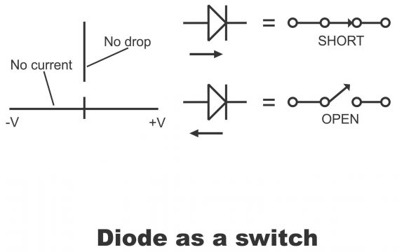
An ideal diode just functions as a switch. When an ordinary switch is turned on or closed, both its contacts combine together, due to which its resistance becomes zero. However, when the switch is turned off (open), an infinite resistance takes place between contacts due to the opening of the contacts. Exactly the same way, when a diode is forward biased, it functions as a closed switch i.e. it practically becomes a diode short circuit. However, when a diode is reversed bias, it offers unlimited resistance, due to which the flow of currents stops completely from within it. Thus, an ideal diode (a diode with no forward drop, nor a reverse flow of current, further with no breakdown on such a diode) is a device or instrument that, just like a switch, acts as a short circuit in the forward direction and as an open circuit in the reverse direction (figure1). Thus, the ideal diode is considered as a bi-stable or two-directional switch, which closes in the forward direction and opens in the reverse direction. Thus, it has two conditions i.e. on or off. In case of high frequency, as a diode turns on or off (due to a rapid change in direction of the cycle)(i.e. it has to change consistently from a conducting condition to a non-conducting condition). Thus, it functions as a switch on high frequency as well. Remember, the on /off of a diode depends on the frequency being provided to the power supply. Suppose, if the value of supply frequency is 50 cycles per second, it turns on or off continuously 50 times. Due to this characteristic of a diode, it assumes the capacity of a switch.

Diode As a Switch Testing
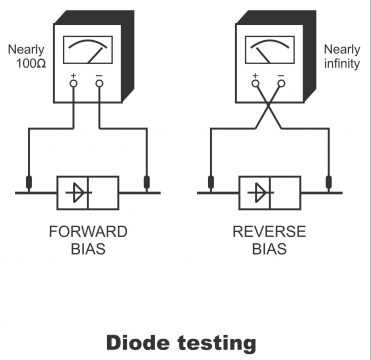
A diode checker or ohmmeter (or ohm meter scale of some multi-meter) is used for checking or testing a diode. For conducting such a test, at least one lead of a diode must be detached from its circuit. Since the ohmmeter has its own DC source; therefore it can bias a diode in the forward or reverse direction. Thus, measurement of both forward and reverse direction resistance in such diodes is possible to carry out. Further, it caters information to a technician about a diodes’ anode and cathode terminals.
The selector switch of an ohmmeter should be set to “Rx100” prior to checking a diode and the leads of the meter should be connected to the diode as per diagram 2. The reading of ohm meter in forwarding direction should be less than 100Ω, while in case of reverse bias, meter reading should be in excess of 5000Ω. It must be borne in mind that when the polarity of an ohmmeter is reversed, the diode’s original resistance values have no importance so long as we can get low and high readings,. In this case, further important points are as under:
- When a diode is checked within a circuit without opening any one of its leads, a common low resistance reading accrues from both directions.
- The diode remains open in case both resistance readings are high
- A diode is short when both resistance readings are low
- If in the reverse direction, a diodes’ resistance is less than being near the maximum value, it is not used in circuits considering it as being leaky.
- A diode is superior only when low resistance reading from one direction and high resistance reading from the other is possible
If we observe the polarity of an ohmmeter while taking resistance reading, the anode and cathode terminals of a good diode can also be determined. Low resistance value results when the positive lead of the meter is connected with the anode (as explained in figure “a”). Thus, in such a situation, the second terminal will be the cathode.

For electronics and programming-related projects visit my YouTube channel.
Previous article: DC Power Supply and Next article: Zener Diodes


