Diy Digital World Clock using Nodemcu ESP8266 and HMI TFT LCD
Table of Contents
Description:
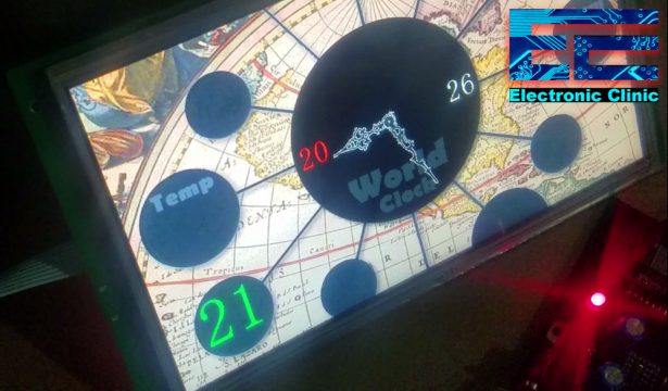
Diy Digital World Clock using Nodemcu ESP8266 and HMI TFT LCD- In this tutorial, you will learn how to make a World Clock using a 10.1 inch HMI TFT LCD display module by the Stone Technologies and a Nodemcu ESP8266 Wifi Module by the ESPRESSIF systems. This is the smartest World clock; you don’t have to enter the hours, minutes, and seconds manually and there is also no need to use the RTC “Real Time Clock” Module.
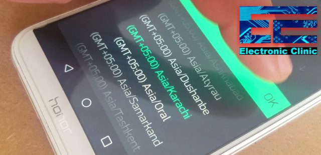
All you need simply select a time zone on your cell phone application designed in Blynk, wait for a minute and the time will be updated.
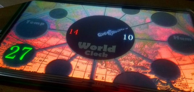
This is the Pakistan’s standard time. The values in Red color are the hours; the value in White color is the minutes, and the values in Green color are the seconds. The time is synchronized with the Server timing after every 1 minute, due to which you will always get the exact time. The synchronization time can be changed in the programming. For the long term use, select 10 minutes or more.
If due to some issues, the Wifi is disconnected the World Clock won’t stop working, the minutes and seconds are incremented automatically and will continue to work. When the wifi connection becomes active the World clock is synchronized again with the server time.
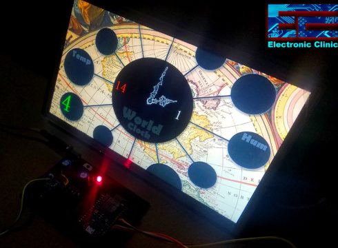
Let’s select a different Time Zone; I am going to select New York America. Simply open the Blynk application, select the time zone and that’s it. After, 1 minute the time will be updated.
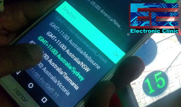
As you can see the time is updated, and now I can keep track of all my favorite Tv shows and movies from Pakistan. Now, let’s check time in Sydney Australia.
After, the time zone is selected, then click on the play button and wait for 1 minute. As you can see in the picture below, the time is updated.
This world clock is based on the 24 hours time format due to which we can easily know if it’s the day time or night time. This is my 5th tutorial on the 10.1 inch HMI intelligent TFT LCD module which is entirely based on my previous 4 tutorials.
In tutorial number1 I explained how to design a graphical user interface using the images designed in Adobe Photoshop. How to use the button function, data variable function, Hardware parameter function and how to use the Drag adjustment, and Slider Scale functions for controlling the screen brightness.
Read Article:
HMI 10.1” TFT LCD Module, Display Panel, and Touchscreen by Stone Technologies
https://www.electroniclinic.com/10-1-hmi-intelligent-tft-lcd-module-display-panel-touchscreen/
In tutorial number 2, I explained the commands used for reading and writing, how to control the user interface without pressing the on screen buttons… how to access the brightness control register and so on.
Read Article:
10.1” HMI intelligent TFT LCD UART Serial Communication “Stone Technologies”
https://www.electroniclinic.com/10-1-hmi-intelligent-tft-lcd-uart-serial-communication/
In tutorial number 3, I explained how to monitor a sensor in real time using Arduino and the HMI Touchscreen TFT LCD display module. In this tutorial I explained in very detail how the Arduino board is interfaced with the HMI TFT LCD module using the MAX232 board.
Read Article:
Arduino HMI intelligent TFT LCD based Sensor Monitoring “Stone Technologies”
https://www.electroniclinic.com/arduino-hmi-tft-lcd-display-sensor-monitoring/
While, in tutorial number 4, I explained how to make a control panel GUI application for the 10.1 inch HMI intelligent TFT LCD module. The Arduino was interfaced with the HMI touchscreen for controlling 220Vac light bulbs.
Read Article:
Arduino 10.1” HMI intelligent TFT LCD 220 Vac Load Controller Panel “Stone Technologies”
https://www.electroniclinic.com/arduino-hmi-tft-lcd-module-electrical-load-controller/
After watching my previous tutorials, you will be able to design any kind of monitoring and control system. So, I highly recommend first watch my previous tutorials and then you can resume from here, as I will be using the same hardware connections, except this time I am using Nodemcu ESP8266 Wifi module instead of using the Arduino. I will explain the modified circuit diagram in a minute.
Without any further delay, let’s get started!!!
Amazon Links:
Other Tools and Components:
Super Starter kit for Beginners
PCB small portable drill machines
eBay store link:
Https://www.ebay.com/str/stonedisplay
Aliexpress store link: https://dwz.cn/PpQlr2RU
*Please Note: These are affiliate links. I may make a commission if you buy the components through these links. I would appreciate your support in this way!
World Clock Circuit Diagram:
As you can see the circuit diagram is really simple. The 10.1 inch TFT LCD and Nodemcu ESP8266 Wifi modules are powered up using a 12v adaptor or battery. All the grounds are connected together. The DIN pin of the TFT LCD module which is data-in is connected with the TX pin of the db9, the DOUT pin which is the data-out pin is connected with the RX pin of the DB9. The VCC pin of the MAX232 board is connected with the 3.3 volts pin of the Nodemcu module, if you remember while using the Arduino I connected the VCC pin of the Max232 board with the 5 volts, as Arduino is a 5 volts microcontroller, while the Nodemcu ESP8266 is a 3.3v controller. So, while using the MAX232 board with the Nodemcu ESP8266 Wifi module, make sure you connect the VCC pin with the 3.3 volts pin. The ground of the MAX232 is connected with the Nodemcu module ground, while the TX and RX pins of the MAX232 Board are connected with the Nodemcu RX and TX pins.
About the Nodemcu ESP8266 Power Supply PCB board and Sponsor:
High quality & Only 24 Hours Build time:
https://www.pcbway.com/setinvite.aspx?inviteid=260737
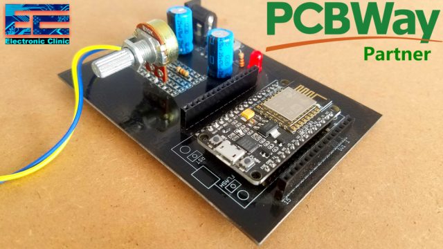
For the easy interfacing I designed a PCB board for the Nodemcu ESP8266 Wifi Module. This PCB is sponsored and manufactured by the PCBway Company, which is one of the most experienced PCB and PCB assembly manufacturer. They create high-quality PCBs at reasonable prices. As you can see the quality is really great, the silkscreen is quite clear and the black solder mask looks amazing. I am 100% satisfied with their work. Now I can easily interface the Nodemcu ESP8266 Wifi module with the 10.1 inch HMI intelligent TFT LCD Module.
Download link of the Nodemcu library for Cadsoft eagle
HMI TFT LCD display module interfacing with Nodemcu ESP8266:
All the connections are done as per the circuit diagram already explained.
RTC “Real Time Clock” Blynk Application:
The step by step Blynk application designing is explained in the video given at the end of this article.
HMI TFT LCD Module World Clock GUI:
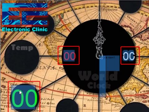
The GUI designing steps are exactly the same as explained in the first video. Following are the 4 images which I designed in Adobe Photoshop.
And the following are the World Clock minute and hour hands.
As usual, I added the data variable functions for displaying the Hours, Minutes, and seconds. The variable memory address of the hours is 0002, the variable memory address of the minutes is 0006, and the variable memory address of the seconds is 0008.
Note: The .bmp file does not upload on the server, so I upload it in zip format.
Minute Hand: minutehand
Hour Hand: hourHand
For rotating the needles I used the rotate icon function and used the icons generated by icon generation tool, which I have already explained in the first video. The only thing you need to know is that it needs 720 steps to complete one revolution and the variable memory addresses of the hour and minute hands which are 0417 and 0422. We will use this information in the Nodemcu programming to control the rotation of the World Clock needles. Now, let’s have a look at the Nodemcu programming.
IoT World Clock Nodemcu ESP8266 Programming using Arduino IDE:
|
1 2 3 4 5 6 7 8 9 10 11 12 13 14 15 16 17 18 19 20 21 22 23 24 25 26 27 28 29 30 31 32 33 34 35 36 37 38 39 40 41 42 43 44 45 46 47 48 49 50 51 52 53 54 55 56 57 58 59 60 61 62 63 64 65 66 67 68 69 70 71 72 73 74 75 76 77 78 79 80 81 82 83 84 85 86 87 88 89 90 91 92 93 94 95 96 97 98 99 100 101 102 103 104 105 106 107 108 109 110 111 112 113 114 115 116 117 118 119 120 121 122 123 124 125 126 127 128 129 130 131 132 133 |
#define BLYNK_PRINT Serial #include <SPI.h> #include <ESP8266WiFi.h> #include <BlynkSimpleEsp8266.h> //#include <BlynkSimpleEsp32.h> #include <TimeLib.h> #include <WidgetRTC.h> // You should get Auth Token in the Blynk App. char auth[] = "CQpqUlW7gUMo08LgUSzpjYXxdtrq25Ab"; // Your WiFi credentials. // Set password to "" for open networks. char ssid[] = "AndroidAP7DF8"; char pass[] = "jamshaid"; BlynkTimer timer; BlynkTimer timer2; WidgetRTC rtc; // for hour hand #define Sensor1_H 0x04 #define Sensor1_L 0x17 //for minute hand #define Sensor2_H 0x04 #define Sensor2_L 0x22 // Hour Value #define Hour_H 0x00 #define Hour_L 0x02 //Minute Value #define Minute_H 0x00 #define Minute_L 0x06 //senconds Value #define Seconds_H 0x00 #define Seconds_L 0x08 int vr = A0; unsigned char sensor1_send[8]= {0xA5, 0x5A, 0x05, 0x82, Sensor1_H, Sensor1_L, 0x00, 0x00}; unsigned char sensor2_send[8]= {0xA5, 0x5A, 0x05, 0x82, Sensor2_H, Sensor2_L, 0x00, 0x00}; unsigned char Hour_send[8]= {0xA5, 0x5A, 0x05, 0x82, Hour_H, Hour_L, 0x00, 0x00}; unsigned char Minute_send[8]= {0xA5, 0x5A, 0x05, 0x82, Minute_H, Minute_L, 0x00, 0x00}; unsigned char Seconds_send[8]= {0xA5, 0x5A, 0x05, 0x82, Seconds_H, Seconds_L, 0x00, 0x00}; int mymints; int myhours; // Digital clock display of the time void clockDisplay() { String currentTime = String(hour()) + ":" + minute() + ":" + second(); String currentDate = String(day()) + " " + month() + " " + year(); int hours = hour(); int minutes = minute(); int seconds = second(); myhours = hour(); mymints = map(minute(),0,59,0,720); if ( (hour() >=0) && ( hour() <= 12) ) { myhours = map(hour(),0,12,0,720); } if ( (hour() >=13) && ( hour() <= 23) ) { myhours = map(hour(),12,23,0,720); } Seconds_send[6] = highByte(seconds); Seconds_send[7] = lowByte(seconds); Serial.write(Seconds_send,8); delay(100); sensor1_send[6] = highByte(myhours); sensor1_send[7] = lowByte(myhours); Serial.write(sensor1_send,8); delay(100); sensor2_send[6] = highByte(mymints); sensor2_send[7] = lowByte(mymints); Serial.write(sensor2_send,8); delay(100); Hour_send[6] = highByte(hours); Hour_send[7] = lowByte(hours); Serial.write(Hour_send,8); delay(100); Minute_send[6] = highByte(minutes); Minute_send[7] = lowByte(minutes); Serial.write(Minute_send,8); delay(100); // Send time to the App Blynk.virtualWrite(V1, currentTime); // Send date to the App Blynk.virtualWrite(V2, currentDate); } BLYNK_CONNECTED() { // Synchronize time on connection rtc.begin(); } void setup() { // Debug console Serial.begin(115200); Blynk.begin(auth, ssid, pass); // Other Time library functions can be used, like: // timeStatus(), setSyncInterval(interval)... // Read more: http://www.pjrc.com/teensy/td_libs_Time.html setSyncInterval(1 * 60); // Sync interval in seconds (10 minutes) // Display digital clock every 10 seconds timer.setInterval(1000L, clockDisplay); } void loop() { Blynk.run(); timer.run(); } |
Nodemcu ESP8266 based World Clock Programming:
#define BLYNK_PRINT Serial
#include <SPI.h>
#include <ESP8266WiFi.h>
#include <BlynkSimpleEsp8266.h>
//#include <BlynkSimpleEsp32.h>
#include <TimeLib.h>
#include <WidgetRTC.h>
All the libraries used in this project can be downloaded by clicking on the download link given below:
// You should get Auth Token in the Blynk App.
char auth[] = “CQpqUlW7gUMo08LgUSzpjYXxdtrq25Ab”;
// Your WiFi credentials.
// Set password to “” for open networks.
char ssid[] = “AndroidAP7DF8”;
char pass[] = “jamshaid”;
Then I defined a timer and rtc.
BlynkTimer timer;
BlynkTimer timer2;
WidgetRTC rtc;
// for hour hand
#define Sensor1_H 0x04
#define Sensor1_L 0x17
//for minute hand
#define Sensor2_H 0x04
#define Sensor2_L 0x22
// Hour Value
#define Hour_H 0x00
#define Hour_L 0x02
//Minute Value
#define Minute_H 0x00
#define Minute_L 0x06
//senconds Value
#define Seconds_H 0x00
#define Seconds_L 0x08
Above are the high bytes and low bytes memory variable addresses used on the graphical user interface side.
unsigned char sensor1_send[8]= {0xA5, 0x5A, 0x05, 0x82, Sensor1_H, Sensor1_L, 0x00, 0x00};
unsigned char sensor2_send[8]= {0xA5, 0x5A, 0x05, 0x82, Sensor2_H, Sensor2_L, 0x00, 0x00};
unsigned char Hour_send[8]= {0xA5, 0x5A, 0x05, 0x82, Hour_H, Hour_L, 0x00, 0x00};
unsigned char Minute_send[8]= {0xA5, 0x5A, 0x05, 0x82, Minute_H, Minute_L, 0x00, 0x00};
unsigned char Seconds_send[8]= {0xA5, 0x5A, 0x05, 0x82, Seconds_H, Seconds_L, 0x00, 0x00};
I have already explained how these commands work. For the extreme basics watch my videos on the uart serial communication and Sensor monitoring, which are available on the Electronic Clinic YouTube channel. These are exactly the same except the memory variable addresses which are changed.
Then I defined two variables mymints and myhours of the type integer.
int mymints;
int myhours;
The clockDisplay() function is a user-defined function, which has no return type and does not take any arguments as the input. The purpose of this function is to access the Current date and time from the Server.
void clockDisplay()
{
String currentTime = String(hour()) + “:” + minute() + “:” + second();
String currentDate = String(day()) + ” ” + month() + ” ” + year();
int hours = hour();
int minutes = minute();
int seconds = second();
myhours = hour();
The hours, minutes, and seconds are accessed from the server using the hour, minute, and second functions.
mymints = map(minute(),0,59,0,720);
As I said earlier one complete rotation is equal to 720 steps and as you know 1 hour is equal to 60 minutes. So using the map function the minutes are adjusted as per the 720 steps.
As the time from the server is in 24 hours format, so we have to find the am and pm. So we simply use the if conditions and set the range just like we did it for the minutes.
if ( (hour() >=0) && ( hour() <= 12) )
{
myhours = map(hour(),0,12,0,720);
}
if ( (hour() >=13) && ( hour() <= 23) )
{
myhours = map(hour(),12,23,0,720);
}
Finally, we store the high bytes and low bytes in their desired memory locations. If in case you find this confusing watch my previous tutorial on the Sensor monitoring.
Seconds_send[6] = highByte(seconds);
Seconds_send[7] = lowByte(seconds);
Serial.write(Seconds_send,8);
delay(100);
sensor1_send[6] = highByte(myhours);
sensor1_send[7] = lowByte(myhours);
Serial.write(sensor1_send,8);
delay(100);
sensor2_send[6] = highByte(mymints);
sensor2_send[7] = lowByte(mymints);
Serial.write(sensor2_send,8);
delay(100);
Hour_send[6] = highByte(hours);
Hour_send[7] = lowByte(hours);
Serial.write(Hour_send,8);
delay(100);
Minute_send[6] = highByte(minutes);
Minute_send[7] = lowByte(minutes);
Serial.write(Minute_send,8);
delay(100);
// Send time to the App
Blynk.virtualWrite(V1, currentTime);
// Send date to the App
Blynk.virtualWrite(V2, currentDate);
}
BLYNK_CONNECTED() {
// Synchronize time on connection
rtc.begin();
}
While rest of the programming is exactly the same; I have been using these instructions in almost all of my IoT based projects.
void setup()
{
// Debug console
Serial.begin(115200);
Blynk.begin(auth, ssid, pass);
// Other Time library functions can be used, like:
// timeStatus(), setSyncInterval(interval)…
// Read more: http://www.pjrc.com/teensy/td_libs_Time.html
setSyncInterval(1 * 60); // Sync interval in seconds (10 minutes)
// Display digital clock every 10 seconds
timer.setInterval(1000L, clockDisplay);
}
void loop()
{
Blynk.run();
timer.run();
}
If you have any questions regarding this project, let me know in a comment.
Watch Video Tutorial:
