DIY Mains frequency meter for 110/220Vac using Arduino
Last Updated on August 18, 2024 by Engr. Shahzada Fahad
Table of Contents
Mains Frequency Meter Project Description:
Mains Frequency Meter– In this Tutorial, you will learn how to make your own 110/220Vac Mains Frequency Meter or a Power line frequency monitoring system using Arduino. This Mains Frequency Meter can also be used with a generator. This is the 3rd part of the SCADA application based grid station parameters monitoring system.
While the Part1 was based on the 110/220V AC voltage monitoring system.
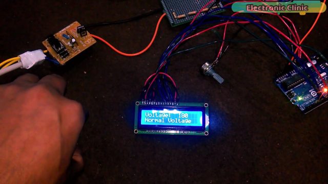
In which I successfully monitored the Normal voltage, over-voltage, and under-voltage. If you want to learn how to make your own AC voltage monitoring system click on the Link Below:
AC Voltage Monitoring “Normal Voltage, Under-Voltage, and Overvoltage”:
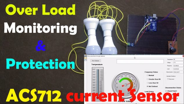
While in Part2 I designed the
Over load monitoring and Protection system using Arduino & ACS712 Current sensor:
Voltage Monitoring and Load Monitoring are also related to the mains/Power lines, so that’s why I covered these parameters as well.
So far we can monitor the voltage and load on our SCADA application, if we increase the voltage above a pre-defined value It will provide automatic disconnection as you can see the led is turned off. Before it was on, and also the box was unchecked which you can see in the picture above.
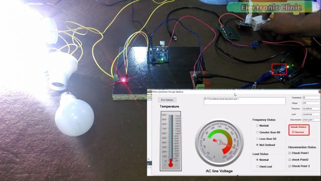
while during the normal voltage the led remains ON. Now if I decrease the voltage below a certain pre-defined value, it will provide automatic disconnection and the led will be turned off, in the same way as it was done for the Over Voltage. At the end, we will connect a relay with pin number 13 so that in case of overvoltage or under voltage the supply can be disconnected to protect our appliances from any damage.
As I said, the 2nd part was based on the Load monitoring system.
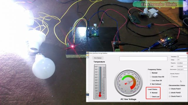
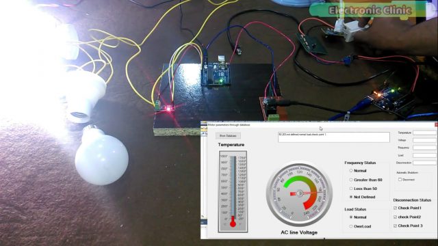
As you can see currently the load status is normal as only one bulb is connected.if I connect another bulb the load will be increased.
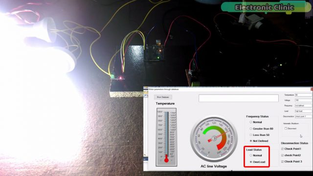
Now you can see on the screen the load status is overload. The load value can be set in the programming as per your requirements. For the practical demonstration watch video given at the end of this Tutorial.
As you know today’s episode is about the Mains Frequency Meter or Power line frequency or Mains frequency Monitoring system. In this tutorial, we will cover
- Complete circuit explanation
- Soldering
- Programming and finally
- Testing
Let’s get started!
Amazon Links:
Arduino Nano USB-C Type (Recommended)
*Disclosure: These are affiliate links. As an Amazon Associate I earn from qualifying purchases.
Circuit Diagram of the Mains Frequency Meter:
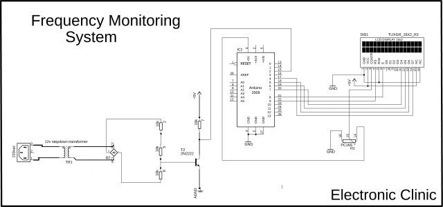
This is the complete Circuit Diagram of the Power line frequency or Mains frequency monitoring system. This schematic is designed in cadsoft eagle9.1.0 version, if you want to learn how to make a schematic and PCB then watch my tutorial:
220v ac is connected with the primary side of the 12v step down transformer. The secondary side of the transformer is connected with the ac legs of the bridge rectifier, while the + and – legs of the rectifier are connected with the series resistors, these resistors are used to reduce the voltage.
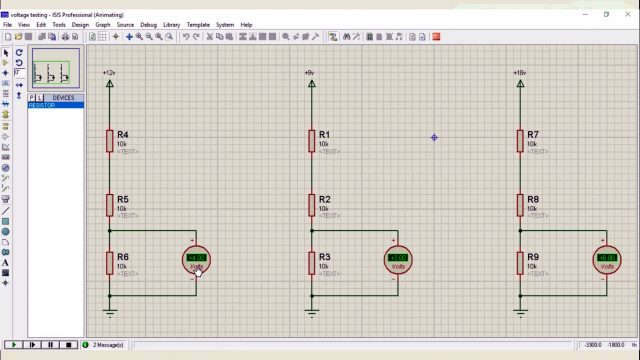
as you can see for 12v we get 4volts which is perfect for the 2n2222 transistor, make sure you never exceed 6volts, as voltage greater than 6 volts can damage the base of 2n2222 NPN transistor, if you get voltage greater than 6 volts then use another resistor in series, it will further reduce the voltage. As you can see in the picture above for different input voltages we get different voltages from the voltage divider circuit.
As you can see in the circuit diagram the emitter of the 2n2222 NPN transistor is connected with the ground, while the collector of the 2n2222 NPN transistor is connected with a 10k resistor, this is a pull-up resistor. A wire from the collector is connected with Pin 2 of the Arduino.
As you can see the ground is connected with pin number 1, 5 and pin number 16 of the LCD. 5v from the Arduino is connected with pin number 2 and pin number 15. The middle pin of the variable resistor or potentiometer is connected with pin number 3 of the LCD. while the other two pins are connected with the ground and 5v. Pin’s 4 to 7 of the Arduino are connected with pins D7 to D4 of the LCD.
Pin number 8 of the Arduino is connected with the enable pin of the LCD. Pin number 9 of the Arduino is connected with the RS Pin of LCD.
Soldering:
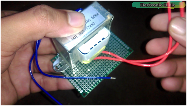
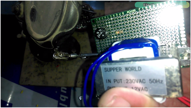
Fix the transformer on a Vero Board using Silicon or screws.
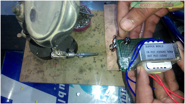
Insert the bridge rectifier into the Vero Board.
Now connect a 10k resistor with the +Ve leg of the bridge rectifier.
Then connect two more resistors in series, connect the last resistor with the ground leg of the bridge rectifier as per the circuit diagram which is already explained.
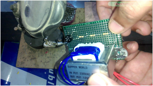
Now connect the secondary wires of the step-down transformer with the ac legs of the bridge rectifier.

Then insert the 2n2222 NPN transistor into the Vero Board, connect a 10k resistor with the collector of the 2n2222 transistor, connect emitter with the ground, and also connect a wire with the collector, which will be then connected with pin number 2 of the Arduino as explained the Circuit diagram.
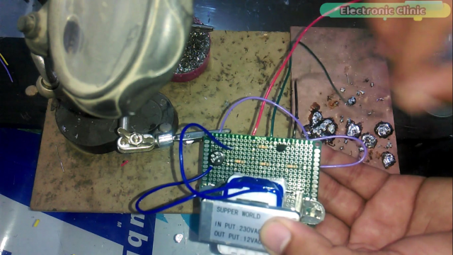
so now you can see the soldering is completed. the black wire which is the ground wire will be connected with the Arduino’s ground, the green wire will be connected with pin number 2 and the red wire will be connected with the Arduino’s 5 volts. One last connection, connect the base of the 2n2222 transistor with the voltage divider circuit. For the LCD soldering watch the following video tutorial.
16×2 LCD Soldering:
Mains Frequency Monitoring Arduino Programming:
|
1 2 3 4 5 6 7 8 9 10 11 12 13 14 15 16 17 18 19 20 21 22 23 24 25 26 27 28 29 30 31 32 33 34 35 36 37 38 39 40 41 42 43 44 45 46 47 48 49 50 51 52 53 54 55 56 57 58 59 60 61 62 63 64 65 66 67 68 69 |
// include the library code: #include <LiquidCrystal.h> #define rs 9 #define en 8 #define d4 7 #define d5 6 #define d6 5 #define d7 4 volatile byte freqcount; unsigned int frequency; unsigned long timeold; int frequency1; // initialize the library with the numbers of the interface pins LiquidCrystal lcd(rs, en, d4, d5, d6, d7); void freq_fun() { //ac cycle, this interrupt function is run twice, so take that into consideration for //calculating frequency //Update count freqcount++; } void setup() { lcd.begin(16, 2); // intialise the LCD Serial.begin(9600); //Interrupt 0 is digital pin 2, so that is where the output from the transistor is connected //Triggers on FALLING (change from HIGH to LOW) attachInterrupt(0, freq_fun, FALLING); freqcount = 0; frequency = 0; timeold = 0; } void loop() { //Update frequency every second delay(1000); //Don't process interrupts during calculations detachInterrupt(0); frequency = 60*50/(millis() - timeold)*freqcount; timeold = millis(); freqcount = 0; Serial.print("Frequency: "); frequency1 = frequency/4; Serial.println(frequency1); //Print out result to lcd lcd.clear(); lcd.print("Frequency="); lcd.print(frequency1); //Restart the interrupt processing attachInterrupt(0, freq_fun, FALLING); } |
Watch Video Tutorial:
Related article:
Nodemcu ESP8266 IOT Mains Frequency Meter:
Discover more from Electronic Clinic
Subscribe to get the latest posts sent to your email.


Fahad Bhai i am Student of Electrical Engineering (6th semester) , I required Some ideas about my FYP I have to submit proposal on 27 AUG 2019.Please Suggest Some Latest Projects Ideas.I am very Confused and have very less knowledge but i want to do at my own.
PLEASE
visit my YouTube Channel and go through all the playlists. I have added so many new projects.