Door Lock System using Arduino and GSM, Wireless Electronic Lock
Last Updated on August 18, 2024 by Engr. Shahzada Fahad
Description:
Door Lock System using Arduino and GSM– In this Tutorial, you will learn how to control an electronic door lock through an SMS using GSM Module and Arduino Uno or Mega. This is a wireless remote controlled electronic lock project, with the help of this project the Door Lock can be controlled from anywhere around the world with the help of a text message consisting of a command to open the Electronic Door Lock. This tutorial covers
- What is an Electronic Lock “E Lock”
- GSM SIM900A Module Pinout and other details
- Complete Circuit Diagram explanation
- Door Lock Arduino Programming and finally
- Testing
Without any further delay, let’s get started!!!
Amazon Purchase links :
Arduino Nano USB-C Type (Recommended)
12v Electronic Door Lock / Elock / Solenoid Lock:
*Disclosure: These are affiliate links. As an Amazon Associate I earn from qualifying purchases.
About the Electronic Lock:

Electronic Locks come in different shapes and sizes. But the working principle of all the Electronic Locks is exactly the same. The difference can only be in the voltage and current it requires to energize the coil of the electronic lock. Inside the electronic lock is the coil which creates the magnetic field when the desired voltage is applied.
The Electronic Locks usually has two wires, the voltage wire, and the GND wire. The Electronic lock that we will be using in this project has two wires. The electronic lock can be checked by applying the voltage across the two wires of the electronic lock.
As this project is based on the GSM, in order to control this Electronic Lock automatically we will need a driver circuit for this Electronic Lock. This electronic Lock can be controlled automatically using a relay, an NPN transistor or a MOSFET. As in this project our only aim to open and close the electronic lock, and as we are not using any PWM or fast switching, so in this project relay is the best choice. Using relay will also provide Isolation.
SIM900A GSM Module:
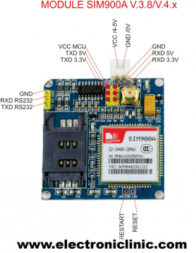
This is the GSM sim900A module, in the market, we have different types of GSM modules, the one I will be using today is sim900A if you want you can also use any other GSM module, like for example sim900D. I have also tested the same programming using sim900D but with a different baud rate, the rest of the program remains the same.
If you are from Pakistan, Bangladesh or India make sure you double-check the GSM module and purchase the unlocked version of the sim900A module. This GSM sim900A module as you can see on the screen has no onboard voltage regulator, so be careful while applying the voltage. Ideal voltage for this GSM module is 4.7v but you can also connect it with a 5v adaptor. If you don’t have a 5v adaptor then you can make your power supply using lm317t adjustable variable voltage regulator, I have a very detailed tutorial on lm317t explaining everything.
As you can see clearly in the picture above this module has so many pins which are clearly labeled, but we will be using only 5 of these pins, the power supply pins, GND, RXD 5v, and TXD 5v. The GND will be connected with the Arduino’s GND, TXD will be connected with the Arduino’s pin number 7 and RXD will be connected with the Arduino’s pin number 8.
Arduino and GSM based Door Lock System Circuit Diagram:

The circuit diagram as you can see is very simple. The electronic lock is controlled using an SPDT “Single Pole Double Throw” type relay, which is a 12v relay. As you can see in the circuit diagram the 12v wire from the power supply is connected with the electronic lock, it really doesn’t matter which wire you connect it to. The other wire of the electronic lock is connected with the normally open contact of the relay. While the ground of the power supply is connected with the common contact of the relay.
This relay is controlled using the relay driver. The relay driver simply consists of the 2n2222 NPN transistor and a 10k resistor. The selection of the transistor depends on the coil current of the electronic lock. To find the current, first you will need to find the resistance of the electronic lock coil, the voltage is already known which is 12v, then using the Ohm’s law
V = IR
The current can be calculated. Now depending on the current value select any NPN transistor whose collector current is greater than the calculated value. For the best performance select a transistor whose collector current is 3 times greater than the calculated value.
As you can see in the circuit diagram above, this relay is controlled using the digital pin 13 of the Arduino, and make sure you connect the ground of the Arduino with the emitter of the 2n2222 NPN transistor.
On the right side you can see a GSM SIM900A module. You can also use SIM900D module. GSM SIM900A module supports Serial communication and that’s why this module is provided with TX and RX pins. As you know very well in Arduino Uno we have only one Serial Port which is on pin number 0 and pin number 1. As I always say never use the Arduino’s default Serial Port for the communication with other devices. The Arduino’s default Serial Port should only be used for debugging purposes. Using the Software Serial library we can define multiple Serial Ports which I will discuss in the Programming.
So Pin number 7 and Pin number 8 of the Arduino will be used as the serial port, that’s why the GSM SIM900A module is connected with the Arduino’s pin number 7 and pin number 8. Pin number 7 is the RX while pin number 8 is the TX. As discussed earlier the recommended voltage of this module is 4.7 to 5 volts. So that’s all about the Circuit Diagram now let’s have a look at the Arduino’s Programming.
Door Lock System Programming:
|
1 2 3 4 5 6 7 8 9 10 11 12 13 14 15 16 17 18 19 20 21 22 23 24 25 26 27 28 29 30 31 32 33 34 35 36 37 38 39 40 41 42 43 44 45 46 47 48 49 50 51 52 53 54 55 56 57 58 59 60 61 |
/* commands b = Open the door " opens the electronic lock" c = close the door */ #include <SoftwareSerial.h> char inchar; // Will hold the incoming character from the GSM shield SoftwareSerial SIM900(7, 8); // gsm module connected here. int load1 = 13; int flag1 = 0; void setup() { Serial.begin(9600); pinMode(load1 , OUTPUT); digitalWrite(load1, LOW); SIM900.begin(9600); // original 19200 randomSeed(analogRead(0)); SIM900.print("AT+CMGF=1\r"); // set SMS mode to text delay(1000); SIM900.print("AT+CNMI=2,2,0,0,0\r"); // blurt out contents of new SMS upon receipt to the GSM shield's serial out delay(1000); SIM900.println("AT+CMGD=1,4"); // delete all SMS delay(5000); Serial.println("Ready..."); } void loop() { if(SIM900.available() >0) { inchar=SIM900.read(); Serial.println(inchar); delay(20); // for LOAD1 if ( (inchar == 'b') && ( flag1 == 0)) { digitalWrite(load1, HIGH); flag1 = 1; } if ( (inchar == 'c') && (flag1 == 1)) { digitalWrite(load1, LOW); flag1 = 0; } } } |
Door Lock System Program Explanation:
/*
Commands
b = Open the door “opens the electronic lock”
c = close the door
*/
To open or close the door you will send b or c in a text message. If you send b in a text messages the door will open and if you only send c in the text message it will close the door.
I started off by including the SoftwareSerial.h header file. This library is used to define multiple serial ports. Using this I defined a serial port on pin number 7 and pin number 8 of the Arduino.
#include <SoftwareSerial.h>
char inchar; // Will hold the incoming character from the GSM shield
SoftwareSerial SIM900(7, 8); // gsm module connected here.
int load1 = 13; //electronic lock is controlled using pin number 13 of the Arduino
int flag1 = 0;
void setup() {
Serial.begin(9600); // activate the serial communication while 9600 is the baud rate
pinMode(load1 , OUTPUT); // load1 which is the electronic lock is set as output
digitalWrite(load1, LOW); // we keep to close by default.
SIM900.begin(9600); // original 19200
randomSeed(analogRead(0));
SIM900.print(“AT+CMGF=1\r”); // set SMS mode to text
delay(1000);
SIM900.print(“AT+CNMI=2,2,0,0,0\r”);
// blurt out contents of new SMS upon receipt to the GSM shield’s serial out
delay(1000);
SIM900.println(“AT+CMGD=1,4”); // delete all SMS
delay(5000);
Serial.println(“Ready…”);
}
void loop() {
if(SIM900.available() >0) // if the gsm module has received a message then
{
inchar=SIM900.read(); // read the message and also print the received character.
Serial.println(inchar);
delay(20);
using the following if conditions we check whether the GSM module has received the character b or c and then accordingly control the Electronic Lock.
// for LOAD1
if ( (inchar == ‘b’) && ( flag1 == 0))
{
digitalWrite(load1, HIGH);
flag1 = 1;
}
if ( (inchar == ‘c’) && (flag1 == 1))
{
digitalWrite(load1, LOW);
flag1 = 0;
}
}
}
Watch Door Lock System Video Tutorial:
Discover more from Electronic Clinic
Subscribe to get the latest posts sent to your email.


Sir what if I use SIM800L gsm module?
Thank you very much >>> You save my final project as technicien in EI >> I have a question if I want to make the programe verify the phone number to accept the sms what should I do >?
I would recommend to use programmable SMS like Twilio… you can create a Studio Flow to filter incoming SMSs
Your project is very nice.So I also want to try your project but I have not program about your project.So, can you give me your project link?