ESP8266 PWM, Nodemcu PWM, Nodemcu PWM Pins, IoT Dimmer, ESP8266 PWM pins, IoT PWM
Table of Contents
Description:
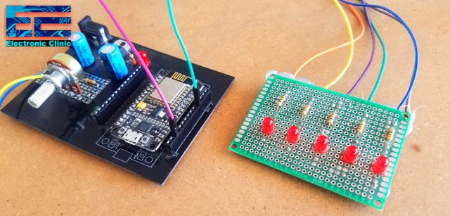
ESP8266 PWM based LED dimmer using IoT– This is a basic getting started tutorial in which you will learn how to use the PWM “Pulse width Modulation” using Nodemcu ESP8266 Wifi Module to control the LED brightness using the Blynk application and a variable resistor or Potentiometer. For the demonstration purposes, I am using an LED that is connected with one of the PWM pins of Nodemcu ESP8266 Wifi Module, but if you want you can also connect a DC motor. The LED brightness can be controlled using a slider from anywhere around the world as this small project is based on IoT technology.
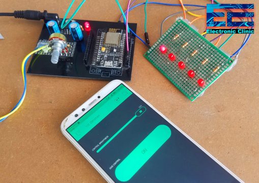
If the give control button is turned ON, then the user won’t be able to control the brightness using the potentiometer. While, when the button is turned ON the LED brightness can only be controlled using the slider. The control between the slider and potentiometer is shifted using the on-screen button.
This tutorial can be easily modified, you can replace the LED with a dc motor and motor driver, this way you will be able to control the speed of a DC motor or you can replace the LED with a Solid State relay and control the brightness of a 110/220Vac light bulb. This project can be used in so many advanced level projects. This is totally up to you how you are going to modify this?
Note: For the practical demonstration and step by step explanation watch video given at the end of this article.
In this tutorial, we will cover
- What are the PWM Pins in the Nodemcu ESP8266 Wifi Module
- Circuit diagram explanation
- Blynk application designing
- Nodemcu ESP8266 wifi module PWM programming and finally
- Testing
Without any further delay let’s get started!!!
Amazon Purchase Links:
Other Tools and Components:
Super Starter kit for Beginners
PCB small portable drill machines
*Please Note: These are affiliate links. I may make a commission if you buy the components through these links. I would appreciate your support in this way!
Nodemcu ESP8266 PWM Pins:
Just like the Arduino Uno, Nodemcu ESP8266 Wifi Module also has the PWM pins. The digital pins D0 to D10 can also be used as the PWM pins which you can confirm by opening the Blynk application. You can use any of these pins.
Nodemcu PWM Circuit Diagram:
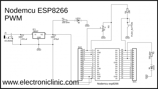
As you can see the circuit diagram is very simple. An LED is connected with the digital pin D4 which is the GPIO pin 2 and is also the PWM pin. A pushbutton is connected with the digital pin D0 of the Nodemcu ESP8266 Wifi Module and is used to turn OFF the LED. The middle leg of the Variable resistor or Potentiometer is connected with the analog pin A0 of the Nodemcu Module, while the other two legs of the variable resistor are connected with 3.3 Volts and ground.
On the left side is the 5v regulated power supply based on the LM7805 Voltage regulator. This power supply is used to power up the Nodemcu ESP8266 Wifi Module. J1 is the female power jack and this is where we connect the input power supply which can be a 12 volts adaptor, a 12 volts battery, or a Solar Panel. Two 470Uf capacitors are connected at the input and output sides of the voltage regulator. The capacitor on the output side of the voltage regulator is really important. A 330-ohm resistor is connected in series with a 2.5v LED. This is a current limiting resistor. A wire from the output of the voltage regulator is connected with the Vin pin of the Nodemcu Module while the ground of the power supply is connected with the ground pin of the Nodemcu ESP8266 Wifi Module. Finally, SV1 and SV2 are the female headers.
Finally, I connected everything as per the circuit diagram. Now let’s make the Blynk application, follow the same exact steps.
Note: this old version of the Blynk app is no more functional. For the blynk mobile App setup and Blynk.cloud dashboard setup ready my article on the New Blynk V2.0. In this article I have explained how to migrate your projects from Blynk 1.0 to the new Blynk V2.0. You can also watch the video.
Nodemcu ESP8266 PWM Blynk Application designing:
- First of all, open the Blynk application.
- Click on the new project and enter the project name as “IoT dimmer” or any other name.
- Click on the choose device and select Nodemcu.
- Make sure the connection type is set to WIFI.
- Finally, click on the create button, an authentication token will be sent on your email id, which later will be used in the PWM Nodemcu
- Click anywhere on the screen and search for the Slider button and add it.
- Now click on the slider button, enter the name as control brightness then click on the output and select D4, turn off the send on release button, turn ON the show value button and finally select 100ms as the write interval.
- Now again click on the screen and this time search for the button and add it.
- Now click on the button, write the name as give control, then click on the output and select the digital pin D1, select the mode as switch. Change the font size if you want.
The blynk application is ready. Now let’s discuss the Nodemcu ESP8266 PWM programming.
Nodemcu ESP8266 PWM Programming:
|
1 2 3 4 5 6 7 8 9 10 11 12 13 14 15 16 17 18 19 20 21 22 23 24 25 26 27 28 29 30 31 32 33 34 35 36 37 38 39 40 41 42 43 44 45 46 47 48 49 50 51 52 53 54 55 56 57 58 59 60 61 62 63 64 65 66 67 68 69 70 71 72 73 74 75 76 77 78 79 80 81 82 83 84 85 86 87 88 89 90 91 92 93 94 95 96 97 98 99 |
// ESP8266 PWM programming // IoT LED dimmer and DC motor speed controller. /* ESP & Blynk */ #include <ESP8266WiFi.h> #include <BlynkSimpleEsp8266.h> #include <SimpleTimer.h> #define BLYNK_PRINT Serial // Comment this out to disable prints and save space char auth[] = "Yz558gb7lZmylfta71ZrxtszvVFPWgYT"; /* WiFi credentials */ char ssid[] = "AndroidAP7DF8"; char pass[] = "jamshaid"; SimpleTimer timer; #define SolidState_Relay 2 // GPIO pin2 corresponds to D4 on physical board "D4 pin on the ndoemcu Module" int PushButton = D0; // Tracks the time since last event fired unsigned long previousMillis=0; unsigned long int previoussecs = 0; unsigned long int currentsecs = 0; unsigned long currentMillis = 0; int interval= 1; // 1 second interval int secs = 0; // current seconds int Vresistor = A0; // to control the brightness manually int VRvalue; // the variable resistor value is stored in VRvalue. void setup() { Serial.begin(115200); Blynk.begin(auth, ssid, pass); pinMode(PushButton, INPUT_PULLUP); pinMode(Vresistor, INPUT); pinMode(SolidState_Relay, OUTPUT); timer.setInterval(1000L, ReadVR); // read variable resistor timer.setInterval(1000L, ReadButton); // read pushbutton } void loop() { timer.run(); // Initiates SimpleTimer Blynk.run(); } void ReadVR() // read variable resistor { if(digitalRead(D1) == 0) { VRvalue = analogRead(Vresistor); // if( VRvalue < 5 ) { VRvalue = 0; } analogWrite(SolidState_Relay, VRvalue); } } void ReadButton() { if(digitalRead(PushButton) == HIGH) { secs = 0; } if(digitalRead(PushButton) == LOW) { currentMillis = millis(); currentsecs = currentMillis / 1000; if ((unsigned long)(currentsecs - previoussecs) >= interval) { secs = secs + 1; if( (secs >= 2)&& (digitalRead(SolidState_Relay) == LOW) ) { digitalWrite(SolidState_Relay, HIGH); } if( (secs >= 2) && (digitalRead(SolidState_Relay) == HIGH) ) { digitalWrite(SolidState_Relay, LOW); } previoussecs = currentsecs; } } } |
Nodemcu ESP8266 PWM Program Explanation:
Before you start the programming, first of all, make sure you download all the necessary libraries by clicking the download button given below.
#include <ESP8266WiFi.h>
#include <BlynkSimpleEsp8266.h>
#include <SimpleTimer.h>
#define BLYNK_PRINT Serial // Comment this out to disable prints and save space
This is the authentication code which was sent via email while making the blynk application. I simply copied the code and paste it over here.
char auth[] = “Yz558gb7lZmylfta71ZrxtszvVFPWgYT”;
/* WiFi credentials */
char ssid[] = “AndroidAP7DF8”; // this is the name of the Wifi router
char pass[] = “jamshaid”; // Password of the Wifi router
then I defined a software based timer.
SimpleTimer timer;
I defined a pin for the LED, which is the gpio pin 2 and is the PWM pin. I selected the pin name as the SolidState_Relay because later I will use the same project for controlling the brightness of a 110/220Vac light bulb using a solid-state relay.
#define SolidState_Relay 2 // GPIO pin2 corresponds to D4 on physical board “D4 pin on the Nodemcu Module”
A pushbutton is connected with the digital pin D0.
int PushButton = D0;
then I defined variables for implementing the timer. So that I can count the seconds.
// Tracks the time since last event fired
unsigned long previousMillis=0;
unsigned long int previoussecs = 0;
unsigned long int currentsecs = 0;
unsigned long currentMillis = 0;
int interval= 1; // 1 second interval
int secs = 0; // current seconds
the potentiometer or variable resistor is connected with the analog pin A0 of the Nodemcu ESP8266 Wifi Module.
int Vresistor = A0; // to control the brightness manually
The value coming from the potentiometer is stored in the variable VRvalue.
int VRvalue; // the variable resistor value is stored in VRvalue.
Inside the void setup() function, first of all, I activated the serial communication using the serial.begin() function and selected 115200 as the baud rate. I will only use this for the debugging purposes. Then I activated the Blynk using the blynk.begin() function which takes three arguments as the input, the authorization token code, the Wifi router name and the password. Then using the pinMode() function I set the pushbutton and variable resistor as the input while the solidstate_relay which is the PWM pin is set as the output. The ReadVR and ReadButton are the user defined functions and are executed after every 1 second. These functions are used to read the variable resistor and to check if the pushbutton is pressed or not.
void setup()
{
Serial.begin(115200);
Blynk.begin(auth, ssid, pass);
pinMode(PushButton, INPUT_PULLUP);
pinMode(Vresistor, INPUT);
pinMode(SolidState_Relay, OUTPUT);
timer.setInterval(1000L, ReadVR); // read variable resistor
timer.setInterval(1000L, ReadButton); // read pushbutton
}
Inside the void loop function, I am only using two functions which are the timer.run() and Blynk.run() functions.
void loop()
{
timer.run(); // Initiates SimpleTimer
Blynk.run();
}
As I said earlier, ReadVR() function is a user defined function. It has no return type and does not take any argument as the input. The purpose of this function is to read the variable resistor and then control the LED brightness.
void ReadVR() // read variable resistor
{
This condition means if the button on the blynk app is turned off then read the variable resistor using the analogRead() function and store the value in variable VRvalue.
if(digitalRead(D1) == 0)
{
VRvalue = analogRead(Vresistor); //
The following if condition means if the value is less than 5 then assign a value of 0 to the VRvalue variable.
if( VRvalue < 5 )
{
VRvalue = 0;
}
Now for implementing the PWM “Pulse Width Modulation” we use the analogWrite() function.
analogWrite(SolidState_Relay, VRvalue);
}
}
ReadButton() function is a user defined function, it has no return type and does not take any arguments as the input.
void ReadButton()
{
This if condition means if the button is not pressed then makes seconds equal to 0.
if(digitalRead(PushButton) == HIGH)
{
secs = 0;
}
This if condition means if the button is pressed and start counting the seconds. if the seconds are greater than or equal to 2 then simply turn ON and turn OFF the LED depending on its current state.
if(digitalRead(PushButton) == LOW)
{
currentMillis = millis();
currentsecs = currentMillis / 1000;
if ((unsigned long)(currentsecs – previoussecs) >= interval) {
secs = secs + 1;
if( (secs >= 2)&& (digitalRead(SolidState_Relay) == LOW) )
{
digitalWrite(SolidState_Relay, HIGH);
}
if( (secs >= 2) && (digitalRead(SolidState_Relay) == HIGH) )
{
digitalWrite(SolidState_Relay, LOW);
}
previoussecs = currentsecs;
}
}
}
In the end, I uploaded the code and start testing the project.
I successfully controlled the LED brightness using the on-screen slider button and the potentiometer. For the practical demonstration watch video given below.
Watch Video Tutorial:

