IOT 3 Phase Transformer Load monitoring using Arduino and Nodemcu
Table of Contents
IoT 3 Phase Transformer Project Description:
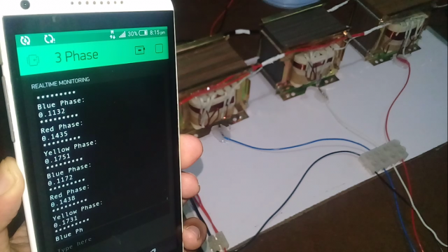
IOT 3 Phase Transformer Load monitoring- In this Tutorial, you will learn how to make a 3 phase transformer load monitoring system using Arduino, Nodemcu esp8266 wifi module and Blynk application. With the help of the Nodemcu module and Blynk application the load on each phase “Red, Yellow, and Blue” can be monitored in real-time from anywhere around the world using your cell phone.
This is the 2nd version of the 3 phase transformer load monitoring system based on IoT “Internet of Things”, while in the first version;
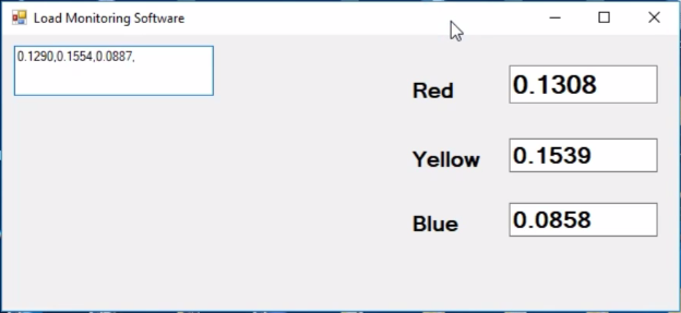
I designed an application in vb.net and used this application to monitor all the three phases of the 3 phase transformer prototype model. The transformer wiring, soldering, the acs712 current sensors connections, soldering, and interfacing is already explained in very detail. For the best understanding, I recommend you should watch my first tutorial on 3 phase transformer load monitoring system and then you can resume from here.
3 Phase Transformer Load Monitoring using Arduino, ACS712, and VB.net:
In this tutorial, I will only explain the modifications which are
- Nodemcu interfacing with Arduino
- Nodemcu programming
- Blynk application designing and finally
- Testing
Amazon Links:
Other Tools and Components:
Super Starter kit for Beginners
PCB small portable drill machines
DISCLAIMER:
Please Note: these are affiliate links. I may make a commission if you buy the components through these links. I would appreciate your support in this way!
Circuit Diagram of the IoT 3 Phase Transformer load monitoring:
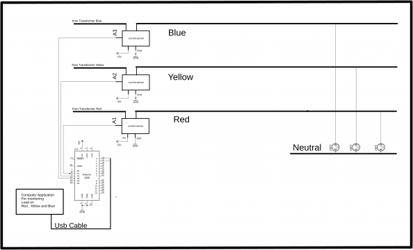
This is the circuit diagram which I used in version 1, which I have already explained in very detailed and the link is given above. As you can see in the Circuit Diagram above three acs712 current sensors are connected with the analog pins A1, A2, and A3.
Three Phases coming from the Transformer are labeled as Red, Yellow, and Blue.
The three bulbs connected with the Red, Yellow, and Blue Phases. Arduino calculates the load and then send the values to the computer application.
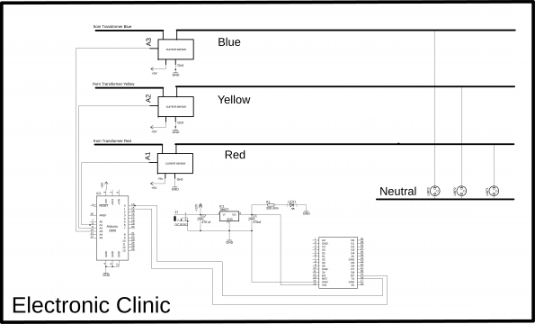
While this is the modified circuit diagram, in which Nodemcu is used. The 5v regulated power supply is based on the lm7805 voltage regulator. Two 470uf capacitors are connected at the input and output of the regulator. A 330-ohm resistor connected in series with a 2.5v led. This is a current limiting resistor, while J1 is the dc female power Jack, this is where we can connect a 12v adaptor or battery. The output of the 7805 Regulator is connected with the Vin pin of the Nodemcu module while the ground is connected with the ground. Connect the TX pin of the Nodemcu module with the RX pin of the Arduino and connect the RX pin of the Nodemcu module with the TX pin of the Arduino and also make sure you connect the ground pin of the Nodemcu module with the ground pin of the Arduino. So this is the only modification that I made in the 2nd version.
Interfacing:
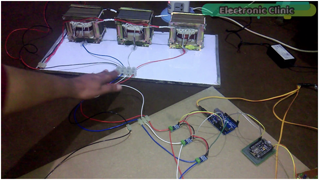
As you can see all the connections are exactly the same as explained in version 1. The Red, Yellow, Blue, and Neutral wires are connected with the PVC Strip connector.
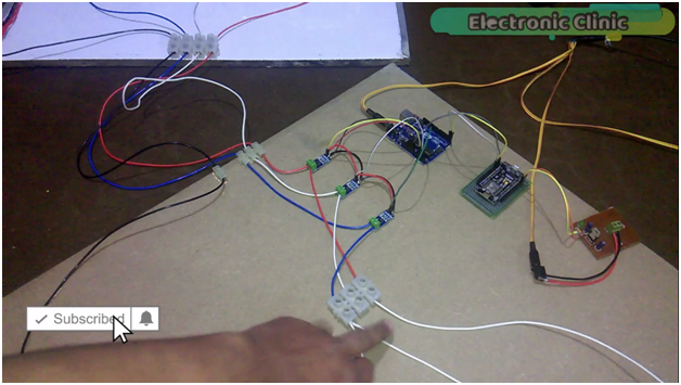
As you can see I am using the same connections, the only modification that I made is the addition of the Nodemcu module and a 5v regulated power supply. This time I am power up the Arduino and Nodemcu module using a 12v adaptor.
While with this PVC strip connector 220vac 100 watt bulbs are connected.
This is the 5v regulated power supply as explained in the circuit diagram. The output of the regulated power supply which is 5v is connected with the Vin pin of the Nodemcu module and the ground of the power supply is connected with the ground of the Nodemcu module. The TX and RX pins of the Nodemcu module are connected with the RX and TX pins of the Arduino. the ground of the Nodemcu module is connected with the ground of the Arduino, while rest of the connections are exactly the same as explained in version 1 of the 3 phase transformer load monitoring system using a Computer application. Now let’s make a blynk application.
Blynk Application Setup for the IOT 3 Phase Transformer:
- First of all, open the blynk application.
- Click on the new project and write the project name.
- Click on choose device and select Nodemcu, and make sure the connection type is set to wifi and then click on the create button, an authentication token will be sent on your email id, simply copy and paste it in the programming.
- Click on the screen and search for the terminal widget and add it.
- Click on the terminal to open the terminal settings, set the terminal name.
- Click on the PIN and select virtual pin V3 and activate the add new line.
- Our basic application setup is completed now discuss the Arduino and Nodemcu programming.
For the detailed explanation and Step by Step making of the Blynk application watch Video Tutorial given at the end of this Article.
Programming of the IOT 3 Phase Transformer Load Monitoring:
This Project is based on two Programs, one Program is written for the Arduino Uno while the other Program is written for the Nodemcu ESP8266 Wifi Module. The Arduino Program as explained in my Previous Tutorial remains the same. Link to the Version1 of the 3 phase transformer load monitoring system is given above.
Arduino Programming:
|
1 2 3 4 5 6 7 8 9 10 11 12 13 14 15 16 17 18 19 20 21 22 23 24 25 26 27 28 29 30 31 32 33 34 35 36 37 38 39 40 41 42 43 44 45 46 47 48 49 50 51 52 53 54 55 56 57 58 59 60 61 62 63 64 65 66 67 68 69 70 71 72 73 74 75 76 77 78 79 80 81 82 83 84 85 86 87 88 89 90 91 92 93 |
#include <stdlib.h> String textForSMS; char buff[10]; const unsigned long sampleTime = 100000UL; // sample over 100ms, it is an exact number of cycles for both 50Hz and 60Hz mains const unsigned long numSamples = 250UL; // choose the number of samples to divide sampleTime exactly, but low enough for the ADC to keep up const unsigned long sampleInterval = sampleTime/numSamples; // the sampling interval, must be longer than then ADC conversion time const int adc_zero = 510; // Red line const int currentPin = 1; // current sensor connected here analog pin A1 float rms; // Yellow line const int currentPin2 = 2; // analog pin A2 float rms2; // Blue Line const int currentPin3 = 3; // analog pin A3 float rms3; String stringrms; String stringrms2; String stringrms3; void setup() { Serial.begin(9600); pinMode(currentPin, INPUT); pinMode(currentPin2, INPUT); pinMode(currentPin3, INPUT); } void loop() { RYB(); // red yellow blue lines checking, its a calling function. textForSMS = textForSMS + stringrms + "," + stringrms2 + "," + stringrms3 +","; Serial.println(textForSMS); delay(1000); textForSMS = ""; } void RYB() // red , yellow , blue lines { unsigned long currentAcc = 0; unsigned int count = 0; unsigned long currentAcc2 = 0; unsigned long currentAcc3 = 0; unsigned long prevMicros = micros() - sampleInterval ; while (count < numSamples) { if (micros() - prevMicros >= sampleInterval) { int adc_raw = analogRead(currentPin) - adc_zero; // user 1 currentAcc += (unsigned long)(adc_raw * adc_raw); // user 1 int adc_raw2 = analogRead(currentPin2) - adc_zero; // user2 currentAcc2 += (unsigned long)(adc_raw2 * adc_raw2); // user 2 int adc_raw3 = analogRead(currentPin3) - adc_zero; // illegal user currentAcc3 += (unsigned long)(adc_raw3 * adc_raw3); // illegal user ++count; prevMicros += sampleInterval; } } rms = sqrt((float)currentAcc/(float)numSamples) * (75.7576 / 1024.0); delay(100); rms2 = sqrt((float)currentAcc2/(float)numSamples) * (75.7576 / 1024.0); delay(100); rms3 = sqrt((float)currentAcc3/(float)numSamples) * (75.7576 / 1024.0); delay(100); stringrms = dtostrf(rms, 1, 4, buff); stringrms2 = dtostrf(rms2, 1, 4, buff); stringrms3 = dtostrf(rms3, 1, 4, buff); //Serial.println("\n"); delay(1000); //Serial.println(currentAcc); // delay(1000); } |
Nodemcu ESP8266 WIFI Module Programming:
|
1 2 3 4 5 6 7 8 9 10 11 12 13 14 15 16 17 18 19 20 21 22 23 24 25 26 27 28 29 30 31 32 33 34 35 36 37 38 39 40 41 42 43 44 45 46 47 48 49 50 51 52 53 54 55 56 57 58 59 60 61 62 63 64 65 66 67 68 69 70 71 72 73 74 75 76 77 78 79 80 81 82 83 84 85 86 87 88 89 90 91 92 93 94 95 96 97 98 99 100 101 102 103 104 105 106 107 108 109 110 111 112 113 114 115 116 117 118 119 120 121 122 123 124 |
//The nodemcu module will be connected with pin 0 and pin 1, on default serial port. //Nodemcu1 programming "car parking slots monitoring" #define BLYNK_PRINT Serial #include <ESP8266WiFi.h> #include <BlynkSimpleEsp8266.h> #include <SoftwareSerial.h> #include <SimpleTimer.h> char auth[] = "5d35963fe5ac40fa9690e382e0a3d0a2"; // Your WiFi credentials. // Set password to "" for open networks. char ssid[] = "ZONG MBB-E8231-6E63"; char pass[] = "08659650"; WidgetTerminal terminal(V3); SimpleTimer timer; String myString; // complete message from arduino, which consistors of snesors data char rdata; // received charactors String l,m,n; // This function sends Arduino's up time every second to Virtual Pin (1). // In the app, Widget's reading frequency should be set to PUSH. This means // that you define how often to send data to Blynk App. void myTimerEvent() { // You can send any value at any time. // Please don't send more that 10 values per second. Blynk.virtualWrite(V1, millis() / 1000); } void setup() { // Debug console Serial.begin(9600); Blynk.begin(auth, ssid, pass); timer.setInterval(1000L,sensorvalue); } void loop() { if (Serial.available() == 0 ) { Blynk.run(); timer.run(); // Initiates BlynkTimer } if (Serial.available() > 0 ) { rdata = Serial.read(); myString = myString+ rdata; Serial.print(rdata); if( rdata == '\n') { // Serial.println(myString); // Serial.println("fahad"); // new code l = getValue(myString, ',', 0); m = getValue(myString, ',', 1); n = getValue(myString, ',', 2); myString = ""; delay(500); // end new code } } } void sensorvalue() { // You can send any value at any time. // Please don't send more that 10 values per second. terminal.println("Red Phase:"); terminal.println(l); terminal.println("*********"); delay(500); terminal.println("Yellow Phase:"); terminal.println(m); terminal.println("*********"); delay(500); terminal.println("Blue Phase:"); terminal.println(n); terminal.println("*********"); delay(500); } String getValue(String data, char separator, int index) { int found = 0; int strIndex[] = { 0, -1 }; int maxIndex = data.length() - 1; for (int i = 0; i <= maxIndex && found <= index; i++) { if (data.charAt(i) == separator || i == maxIndex) { found++; strIndex[0] = strIndex[1] + 1; strIndex[1] = (i == maxIndex) ? i+1 : i; } } return found > index ? data.substring(strIndex[0], strIndex[1]) : ""; } |
Nodemcu Program explanation:
Before you start the programming for the IOT 3 Phase Transformer Load Monitoring System, first of all, make sure that you download all the necessary libraries and you install the Nodemcu board and you also install a driver for the USB UART.
|
1 2 3 4 5 6 7 8 9 10 11 12 13 14 15 16 17 18 19 20 21 22 23 24 25 26 27 |
char auth[] = "5d35963fe5ac40fa9690e382e0a3d0a2"; //This is the authentication number which was sent via email, I simply copied and past it over here. char ssid[] = "ZONG MBB-E8231-6E63"; // This is the name of your wifi router. char pass[] = "08659650"; //And this is the password. WidgetTerminal terminal on virtual pin V3. String myString; // the mystring variable is used to store the complete message. char rdata; // the variable rdata is used to receive each and every character which is sent serially by the arduino. then I defined three variables l, m and n of the type string. these variables will be used to store the values of red, yellow and blue phases. Serial.begin(9600); // activates the serial communication. 9600 is the baud rate Sensorvalue is a user defined function and is executed every 1 second. if (Serial.available() == 0 ) // if Nodemcu module hasn’t received any data from the arduino then simply keep executing these two function. if (Serial.available() > 0 ) //if nodemuc module has received data then simply read the serial port, and add each character with mystring to make a complete message. if( rdata == '\n') |
This condition make sure that the entire message is received.The entire message which is received is split using the getvalue function, which is a user defined function. Each value is then stored in variables l , m and n. these values are basically the RMS values of the Red, Yellow, and Blue phases. At the end we empty the string for new data and use a delay of half second.Sensor value is a user-defined function and is used to send the text messages and values to the blynk terminal.Getvalue is a user-defined function and it takes three arguments as the input, data, separator and the index. This function is used to split the string message using a comma as the delimiter.If you have missed anything, you can watch the following video Tutorial. If you have any Questions let me know in a comment. Subscribe my YouTube channel.
