Max30100 pulse Oximeter Arduino Code, circuit, and Programming
Last Updated on August 17, 2024 by Engr. Shahzada Fahad
Table of Contents
Description:
Max30100 pulse Oximeter Arduino– In this tutorial, you will learn how to use the Max30100 Pulse Oximeter with Arduino and display the Heart Rate and Blood Oxygen on a 16×2 LCD. The Heart rate or Pulse rate or Heartbeat is measured in BPM which is also known as the beats per minute while the Blood Oxygen Concentration is measured in percentage.
So, basically, the max30100 sensor is a Pulse Oximetry and heart rate monitor which is used to check the health of a person with any condition that affects blood oxygen levels, such as:
- Heart Attack
- Heart failure
- Lungs Cancer
- Asthma etc.
Recently, I posted another article “Bluetooth Pulse Oximeter using Max30100, and Arduino Nano, SpO2 and BPM
” in which I displayed the Blood Oxygen and Heart Rate values on the I2C supported 16×2 LCD and also sent the Blood Oxygen and BPM values to the Android cell phone application.

What is Pulse Oximetry?
Pulse Oximetry is a test used to measure the oxygen level i.e. oxygen saturation of the blood. It is an easy, painless measure of how well oxygen is being sent to parts of your body furthest from your heart, such as the arms and legs. What to study more about the health care visit “https://www.hopkinsmedicine.org/”.
No doubt the Max30100 Pulse Oximeter is an amazing sensor, still it has some disadvantages it may generate incorrect readings if the finger is not properly placed. The ambient light falling on the sensor can affect the final reading. While using the Max30100 Oximeter, make sure your finger is not moving because it can result in an incorrect reading. One more thing that you really need to take care of while using the Max30100 Sensor is that, never press the sensor too hard as this affects the blood flow and as a result you will get incorrect readings. Try to place your finger softly and make sure your finger does not move, this way you can get the most accurate reading.
This is my first getting started tutorial on the Max30100 pulse Oximeter which covers the extreme basics including
- Max30100 Pulse Oximeter technical specification
- Max30100 sensor Pinout
- Interfacing Max30100 Pulse Oximeter Sensor with Arduino
- Programming and finally
- Testing
Without any further delay let’s get started!!!
Amazon Links:
Arduino Nano USB-C Type (Recommended)
*Disclosure: These are affiliate links. As an Amazon Associate I earn from qualifying purchases.
How an Oximeter works?
Oxygen Saturation
Pulse Oximeter measure oxygen saturation. Before we learn the principles of how pulse Oximeter work, we need to have an understanding of what oxygen saturation is. Oxygen enters the lungs and then is passed on into blood. The blood carries the oxygen to the various organs in our body. The main way oxygen is carried in our blood is by means of hemoglobin. The hemoglobin without oxygen we will call de oxygenated hemoglobin (deoxy Hb). The hemoglobin with oxygen, we will call oxygenated hemoglobin (oxy Hb).
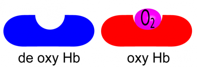
Oxygen saturation simply refers to the percentage of the available hemoglobin that carries oxygen. Take the situations below. There are 16 hemoglobin units and none of the 16 have oxygen. The oxygen saturation is therefore 0 %.

And if it carries the 75% oxygen
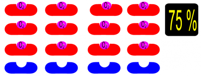
And if all the blood cells carries the oxygen then of course it is going to be 100%.

The Oximeters come in different shapes and sizes, but the overall working principle of the pulse Oximeters is exactly the same. Some are of the clip type like the one you can see in the picture above, while some works on the reflection technique, as the one I am using works on the reflection. So when the light passes or reflects we can measure the Oxygen concentration.
For more details visit https://www.howequipmentworks.com/pulse_oximeter/. This is really an amazing article that really helped me in understanding the working principle of the Oximeter.
About the Max30100 Pulse Oximeter Sensor:
General Description:
The MAX30100 is an integrated pulse Oximetry and heartrate monitor sensor solution. It combines two LEDs, a photodetector, optimized optics, and low-noise analog signal processing to detect pulse Oximetry and heart-rate signals.
There is another type of the Max30100 pulse Oximeter as you can see in the picture below,

This type of the Oximeter has the sensors and electronic components all on the same side, moreover there are many complaints about this type of the sensor. I recommend you should purchase the one I am using in this tutorial. Because, while using this sensor you don’t need to remove the resistors or solder any extra wires.
SpO2 Subsystem
The SpO2 subsystem in the MAX30100 is composed of ambient light cancellation (ALC), 16-bit sigma delta ADC, and proprietary discrete time filter.
The SpO2 ADC is a continuous time oversampling sigma delta converter with up to 16-bit resolution. The ADC out-put data rate can be programmed from 50Hz to 1kHz. The MAX30100 includes a proprietary discrete time filter to reject 50Hz/60Hz interference and low-frequency residual ambient noise.
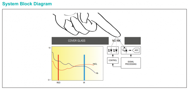
As per the system block diagram which is available in the datasheet, it clearly shows that there should be small distance between the sensor and finger.
Max30100 Pulse Oximeter Sensor Technical Specification:
The MAX30100 operates from 1.8V and 3.3V power supplies.
Applications
- Wearable Devices
- Fitness Assistant Devices
- Medical Monitoring Devices
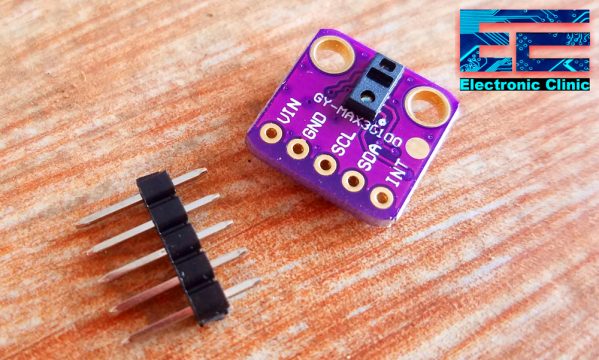
Max30100 Pulse Oximeter Sensor Pinout:
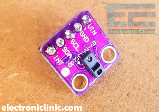
As you can see clearly the GY-Max30100 Pulse Oximeter has a total of 5 male headers which are clearly labeled as VIN, GND, SCL, SDA, and INT. This is an i2c supported sensor and communicates with the Arduino board through i2c communication bus.
Interfacing Max30100 Pulse Oximeter Sensor with Arduino Circuit Diagram:
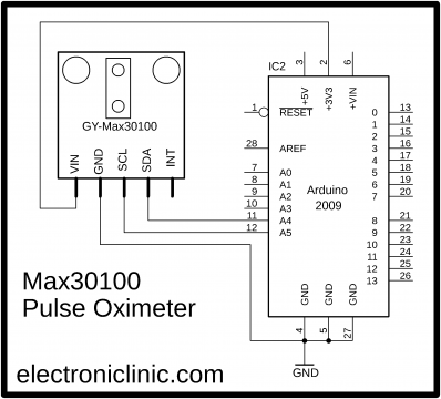
First let’s start with a very basic circuit diagram. As you can see the VIN and GND pins of the Max30100 sensor are connected with the Arduino’s 3.3v and GND pins. The SCL pin is connected with the Analog pin A5, SDA pin is connected with the Analog pin A4. While the INT pin is not connected.
Download: Max30100 Datasheet
Max30100 Pulse Oximeter Arduino Code / Programming:
Download: Max30100 pulse Oximeter Arduino Library
|
1 2 3 4 5 6 7 8 9 10 11 12 13 14 15 16 17 18 19 20 21 22 23 24 25 26 27 28 29 30 31 32 33 34 35 36 37 38 39 40 41 42 43 44 45 46 47 |
#include <Wire.h> #include "MAX30100_PulseOximeter.h" #define REPORTING_PERIOD_MS 1000 PulseOximeter pox; uint32_t tsLastReport = 0; void onBeatDetected() { Serial.println("Beat!"); } void setup() { Serial.begin(115200); Serial.print("Initializing pulse oximeter.."); // Initialize the PulseOximeter instance // Failures are generally due to an improper I2C wiring, missing power supply // or wrong target chip if (!pox.begin()) { Serial.println("FAILED"); for(;;); } else { Serial.println("SUCCESS"); } pox.setIRLedCurrent(MAX30100_LED_CURR_7_6MA); // Register a callback for the beat detection pox.setOnBeatDetectedCallback(onBeatDetected); } void loop() { // Make sure to call update as fast as possible pox.update(); if (millis() - tsLastReport > REPORTING_PERIOD_MS) { Serial.print("Heart rate:"); Serial.print(pox.getHeartRate()); Serial.print("bpm / SpO2:"); Serial.print(pox.getSpO2()); Serial.println("%"); tsLastReport = millis(); } } |
This is a simple program which sends the BPM “beats per minute” and Blood Oxygen values to the serial monitor.
While the Arduino board is connected with the laptop, open the serial monitor and select the desired baud rate as specified in the programming.
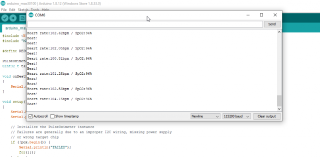
As you can see I can successfully read the BPM and Blood oxygen value percentage. Now let’s print these values on the LCD.
Interfacing Max30100 Pulse Oximeter Sensor and 16×2 LCD with Arduino Circuit Diagram:

This is the modified circuit diagram. The max30100 pulse Oximeter sensor connection with the Arduino remain the same. This time I added a 16×2 LCD. As you can see, pin number 1 and pin number 16 are connected with the Arduino’s ground. Pin number 2 and pin number 15 are connected with the Arduino’s 5 volts. Pin number 3 is the contrast pin and is connected with the middle leg of the potentiometer this is used for the LCD contrast adjustment.
The RS pin of the LCD is connected with the Arduino’s pin number 9, R/W pin is connected with the ground, Enable pin is connected with the Arduino’s pin number 8. Pins D4 to D7 of the 16X2 LCD are connected with the Arduino’s pins 7, 6, 5, and 4.
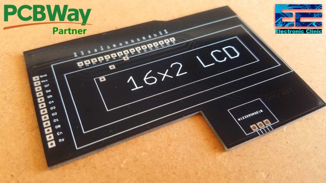
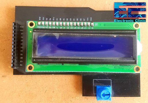
For the easy interfacing, I designed a PCB board for the 16×2 LCD module. This PCB is manufactured by the PCBway Company. As you can see the quality is really great, the silkscreen is quite clear and the black solder mask looks amazing. I am 100% satisfied with their work.
Download the 16×2 LCD PCB board Gerber files:
Download
High quality & Only 24 Hours Build time
This is how the 16×2 PCB board looks after soldering. Now, I can easily interface this 16×2 LCD module with Arduino.
I interfaced the LCD and Max30100 pulse Oximeter as per the circuit diagram already explained. Now let’s have a look at the Arduino programming.
Arduino program to Display the Oxygen percentage and BPM on the LCD:
|
1 2 3 4 5 6 7 8 9 10 11 12 13 14 15 16 17 18 19 20 21 22 23 24 25 26 27 28 29 30 31 32 33 34 35 36 37 38 39 40 41 42 43 44 45 46 47 48 49 50 51 52 53 54 55 56 57 58 59 60 61 62 63 64 65 66 |
#include <Wire.h> #include "MAX30100_PulseOximeter.h" #include <LiquidCrystal.h> #define REPORTING_PERIOD_MS 1000 #define rs 9 #define en 8 #define d4 7 #define d5 6 #define d6 5 #define d7 4 // initialize the library with the numbers of the interface pins LiquidCrystal lcd(rs, en, d4, d5, d6, d7); PulseOximeter pox; uint32_t tsLastReport = 0; void onBeatDetected() { Serial.println("Beat!"); } void setup() { Serial.begin(115200); Serial.print("Initializing pulse oximeter.."); // set up the LCD's number of columns and rows: lcd.begin(16, 2); // Print a message to the LCD. lcd.print("Oximeter"); // Initialize the PulseOximeter instance // Failures are generally due to an improper I2C wiring, missing power supply // or wrong target chip if (!pox.begin()) { Serial.println("FAILED"); for(;;); } else { Serial.println("SUCCESS"); } pox.setIRLedCurrent(MAX30100_LED_CURR_7_6MA); // Register a callback for the beat detection pox.setOnBeatDetectedCallback(onBeatDetected); } void loop() { // Make sure to call update as fast as possible pox.update(); if (millis() - tsLastReport > REPORTING_PERIOD_MS) { lcd.clear(); lcd.setCursor(0,0); lcd.print("BPM: "); lcd.print(pox.getHeartRate()); lcd.setCursor(0,1); lcd.print("SpO2: "); lcd.print(pox.getSpO2()); lcd.print("%"); tsLastReport = millis(); } } |
This is the same exact program with very little modification. I added the LiquidCrystal library and defined pins as per the circuit diagram. In the void loop function, I added instructions for displaying the oxygen percentage and BPM values on the LCD.
For the practical demonstration and step by step explanation watch video given below.
Watch Video Tutorial:
Discover more from Electronic Clinic
Subscribe to get the latest posts sent to your email.


I have a problem with the library
if i compile in arduino I have folowing error :
oximeter.ino:2:36: fatal error: MAX30100_PulseOximeter.h: Bestand of map bestaat niet ( file non existing)
i have loaded correctly the lib file in arduino
Thank u..it helped me to fix my project
I have an Arduino NANO v3 , is possible assembly the project with this board?
Hello, this is great tutorial! I’m beginner in this field so i want to ask something. What is the function of pin INT in the sensor? Why you didn’t use it? Thank you.
Can same libraries be use same to Lilypad Arduino?
I have never used Lilypad, i will order it soon.
Please, I need the max 30100 sensitive library for a proteus program.
Can anyone please explain how do the laser emitted by max30100 are reflected into the finger? Does it involve the nail as a reflection surface?
Same query I’ve ,if you get answer then plz let me know
A good blog always comes-up with new and exciting information and while reading I have feel that this blog is really have all those quality that qualify a blog to be a one