Bluetooth Pulse Oximeter using Max30100, and Arduino Nano, SpO2 and BPM
Last Updated on August 17, 2024 by Engr. Shahzada Fahad
Table of Contents
Bluetooth Pulse Oximeter Max30100, Description:
Bluetooth Pulse Oximeter using Max30100, and Arduino Nano– In this tutorial, you will learn how to use the Max30100 Pulse Oximeter with Arduino Nano and display the Heart Rate and Blood Oxygen on a 16×2 I2C supported LCD Module and also send the blood oxygen and heart rate or Pulse rate values to the android application designed in Android Studio using the wireless Bluetooth technology. The Heart rate or Pulse rate or Heart beat is measured in BPM which is also known as the beats per minute while the Blood Oxygen Concentration is measured in percentage.

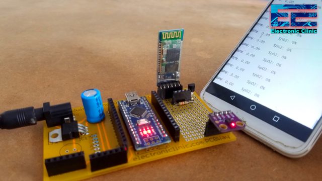
In this picture above you can see the BPM and SpO2 values on the I2C supported 16×2 LCD. You can also monitor the same values on the android cell phone application.

If you are near to the circuit, you can directly read the Blood Oxygen and BPM values on the LCD, and if away, then you can use your android cell phone application and monitor the Blood Oxygen and BPM values wirelessly.
About the Sponsor, PCBWay:

High quality & Only 24 Hours Build time
The PCB boards used in this project is sponsored by the PCBWay Company. Only 5 dollars for 10 PCBs and 30 dollars in total for 20 PCBs Assembly. Besides this PCBWay also provides a great variety of services including Aluminum PCB, Rigid-Flex, Metal Core, flexible, High Frequency, High-TG, Thick-Copper, HDI, and LED PCBs. The sign up process hardly takes 1 minute and you are welcomed with a 5 dollars welcome bonus, what are you waiting for go and get your first prototype order for free.
You can also disconnect the LCD and only use the Android cell phone application for monitoring. You can use any of these two, or you can use both at the same time for monitoring the BMP and Blood Oxygen values SpO2.
So, basically the max30100 sensor is a Pulse Oximetry and heart rate monitor which is used to check the health of a person with any condition that affects blood oxygen levels, such as:
- Heart Attack
- Heart failure
- Lungs Cancer
- Asthma etc.
I have already explained the very basics in my first article on the Max30100 Pulse Oximeter “Getting started with Max30100 Pulse Oximeter”. In this tutorial I interfaced the Max30100 pulse Oximeter with Arduino Uno and displayed the Blood Oxygen and Heart Rate information on the 16×2 LCD module and also fixed some of the common issues. I highly recommend read my previous article on the Max30100.
To take this project to another level and to reduce the wiring, and to make it more user friendly, I decided to use the i2c 16×2 LCD display module and the HC05 or HC06 Bluetooth Module to wirelessly monitor the Blood Oxygen and Heart Rate values using a Bluetooth supported android cell phone application.
I have tried my level best to keep everything simple by modifying the previous circuit diagram and Arduino code. So, I highly recommend read my previous articles on the Max30100 pulse Oximeter, I2C 16×2 LCD, and HC05 or HC06 Bluetooth.
You can also follow my tutorials on how to design android cell phone applications for monitoring sensors and controlling electrical devices. After, reading these two article, you will be able to design your own android cell phone applications.
In this tutorial, we will cover,
- Modified circuit diagram using Bluetooth, i2c supported 16×2 LCD, and Arduino Nano.
- Interfacing and soldering the components
- Modified Arduino code, and finally
- Testing
Without any further delay, let’s get started!!!
Amazon Purchase Links:
Arduino Nano USB-C Type (Recommended)
*Disclosure: These are affiliate links. As an Amazon Associate I earn from qualifying purchases.
Android Application:
The android application used for monitoring the Blood Oxygen and Heart rate values is available free of cost.
Max30100 Pulse Oximeter Sensor:

This is the Max30100 Pulse Oximeter used for measuring the Blood Oxygen and Heart Rate.

As per the system block diagram which is available in the datasheet, it clearly shows that there should be small distance between the sensor and finger.
Max30100 Pulse Oximeter Sensor Technical Specification:
The MAX30100 operates from 1.8V and 3.3V power supplies.
Max30100 Applications
- Wearable Devices
- Fitness Assistant Devices
- Medical Monitoring Devices
Pinout of the Max30100 Pulse Oximeter:
As you can see clearly the GY-Max30100 Pulse Oximeter has a total of 5 male headers which are clearly labeled as VIN, GND, SCL, SDA, and INT. This is an i2c supported sensor and communicates with the Arduino board through i2c communication bus.
I2C supported 16×2 LCD Module:

This is an i2c supported 16×2 LCD display module. The Max30100 pulse Oximeter also uses the i2c bus. So using only two pins A4 and A5 “SDA and SCL” we can communicate with both the modules. If you want to know in detail about the i2c supported 16×2 LCD Display module, like its libraries, fixing the basic issues, etc then read my article on how to use the i2c supported 16×2 LCD with Arduino.
This is a regular 16×2 LCD module with an I2C converter attached on the backside of the LCD. This I2C converter can also be purchased separately. Using this I2C converter you can convert any 16×2 LCD into an I2C LCD.
Interfacing Max30100, I2C 16×2 LCD, and Bluetooth with Arduino Nano:

This is the modified circuit diagram. The Arduino Nano is powered up using the 5V regulated power supply based on the LM7805 voltage regulator. J1 is the DC female power jack. This is where you can connect a 12V adaptor, Battery, or a Solar Panel. Make sure the power supply voltage does not exceed the input voltage limit of the LM7805 voltage regulator. The regulated voltage is then connected with the VIN pin of the Arduino Nano. Don’t forget to connect the GND of the power supply with the ground pin of the Arduino board.
The max30100 pulse Oximeter sensor connection with the Arduino remains the same. This time I added an i2c supported 16×2 LCD. The SDA and SCL pins of the 16×2 LCD are connected with the Arduino’s analog pins A4 and A5. While the VCC and GND pins of the LCD I2C Converter are connected with the 5V and GND.
The RX and TX pins of the HC05 Bluetooth module are connected with the Arduino pin’s 2 and 3. While the GND and +5V pins of the Bluetooth module are connected with GND and 5 volts of the Arduino.

Next, I designed a PCB for the Arduino Nano, which I will use as the Development board. I added female headers for the 3.3V, 12V, 5V, and ground. The right side area can be used as the Vero Board for soldering other electronic components. I also added female headers on the left and right sides of the Arduino Nano for connecting the jumper wires. I double checked all the connections. And finally, generated the Gerber files and placed an online order on the PCBWay official website.
Learn how to generate Gerber files, and how to view Gerber Files?
Interfacing Max30100, Bluetooth, and 16×2 i2c LCD with Arduino Nano:

These are the PCB boards I received from the PCBWay Company. As you can see the Quality is really great. The silkscreen is quite clear and the solder mask looks amazing. Next, I started off by placing the components and completed the soldering job. For the soldering watch my video tutorial given at the end of this article.

Finally, I connected the I2C supported 16×2 LCD, Max30100 Pulse Oximeter, and the HC05 Bluetooth module.
Bluetooth Pulse Oximeter Max30100 Arduino programming:
|
1 2 3 4 5 6 7 8 9 10 11 12 13 14 15 16 17 18 19 20 21 22 23 24 25 26 27 28 29 30 31 32 33 34 35 36 37 38 39 40 41 42 43 44 45 46 47 48 49 50 51 52 53 54 55 56 57 58 59 60 61 62 63 64 65 66 67 68 69 70 71 72 73 74 75 76 77 78 79 80 81 82 83 84 85 |
/* Download Libraries: https://www.electroniclinic.com/arduino-libraries-download-and-projects-they-are-used-in-project-codes/ */ #include <Wire.h> #include <SoftwareSerial.h> #include <LiquidCrystal_I2C.h> LiquidCrystal_I2C lcd(0x27,16,2); //0x27 is the i2c address, while 16 = columns, and 2 = rows. #include "MAX30100_PulseOximeter.h" SoftwareSerial blue(2,3); // bluetooth module connected here #define REPORTING_PERIOD_MS 1000 PulseOximeter pox; uint32_t tsLastReport = 0; void onBeatDetected() { Serial.println("Beat!"); } void setup() { Serial.begin(115200); blue.begin(9600); lcd.init(); //Init the LCD lcd.backlight(); //Activate backlight lcd.home(); Serial.print("Initializing pulse oximeter.."); // Initialize the PulseOximeter instance // Failures are generally due to an improper I2C wiring, missing power supply // or wrong target chip if (!pox.begin()) { Serial.println("FAILED"); for(;;); } else { Serial.println("SUCCESS"); } pox.setIRLedCurrent(MAX30100_LED_CURR_7_6MA); // Register a callback for the beat detection pox.setOnBeatDetectedCallback(onBeatDetected); } void loop() { Serial.println("what"); // Make sure to call update as fast as possible pox.update(); if (millis() - tsLastReport > REPORTING_PERIOD_MS) { // to android cell phone application blue.print("BPM: "); blue.print(pox.getHeartRate()); //blue.println("\n"); blue.print(" SpO2: "); blue.print(pox.getSpO2()); blue.print("%"); blue.println("\n"); // to 16x2 LCD lcd.clear(); lcd.setCursor(0,0); lcd.print("BPM: "); lcd.print(pox.getHeartRate()); lcd.setCursor(0,1); lcd.print("SpO2: "); lcd.print(pox.getSpO2()); lcd.print("%"); tsLastReport = millis(); } } |
This is the same exact program with a very little modification. I added the I2C supported LiquidCrystal library and defined pins as per the circuit diagram. In the void loop function I added instructions for sending the BPM and Oxygen Percentage values to the android cell phone application; and also added instructions for displaying the BPM and Oxygen percentage values on the I2C supported 16×2 LCD module.
Watch Video Tutorial:
Discover more from Electronic Clinic
Subscribe to get the latest posts sent to your email.


On display no readings showing sir