Nodemcu esp8266 notification message & real time monitoring using Blynk
Table of Contents
ESP8266 Notification Message, Project Description:
ESP8266 notification message- In this Tutorial, you will learn how to make a message notification system using Arduino, Nodemcu esp8266 wifi module, and Blynk application.
We have been using GSM modules for notification or Alert messages. GSM modules are most commonly used for monitoring the sensors. Whenever the sensor value exceeds a pre-defined value a notification message is sent to the owner. A major problem with the GSM module is that you cannot monitor the sensors in real-time, as sending and receiving a message takes time.
This problem of monitoring the sensor in real-time can be solved by using the Nodemcu module. With the help of the Nodemcu module, you can monitor the sensors in real-time, and also it can be programmed to send notification or alert messages whenever a pre-defined value is exceeded, so this way you don’t need to monitor the values all the time. One of the major advantages of using the notification widget in Blynk application is that, even if the application is running in the background, still you are informed through a notification message. Which at this point works just like the GSM module.
Note: this old version of the Blynk app is no more functional. For the blynk mobile App setup and Blynk.cloud dashboard setup ready my article on the New Blynk V2.0. In this article I have explained how to migrate your projects from Blynk 1.0 to the new Blynk V2.0. You can also watch the video.
Amazon Links:
Other Tools and Components:
Super Starter kit for Beginners
PCB small portable drill machines
*Please Note: These are affiliate links. I may make a commission if you buy the components through these links. I would appreciate your support in this way!
Nodemcu ESP8266 interfacing with Arduino, Circuit Diagram:
Nodemcu esp8266 notification message
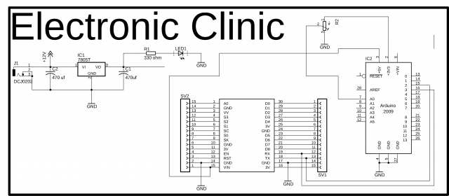
So this is the final circuit that we will be using today. If you are using Nodemcu with Arduino or mega and you are not using many sensors then you don’t need this power supply, you can power up the Nodemcu module using Arduino or mega…let me tell you once again, if you are using many sensors then I recommend you should use a separate power supply for this. Let’s have a look at the complete circuit diagram.
This schematic is designed in Cadsoft eagle 9.1.0 version. If you want to learn how to make a schematic and PCB then watch my tutorial.
This is the 5v regulated power supply based on the lm7805 voltage regulator. As I said earlier if you are not using many sensors then you don’t need this power supply. In this project as we will be using only one sensor which is a variable resistor, so that’s why we don’t need this power supply, that’s why the Vin pin of the Nodemcu is connected with the Arduino’s 5v, and the ground pin of the Nodemcu is connected with the Arduino’s ground. But if you have connected many sensors then simply connect a wire from the output of the voltage regulator with the Vin pin of the Nodemcu.
As the Nodemcu will communicate with Arduino through serial communication, so for this we need a serial port, as I always say never use the Arduino’s default serial port for communication with other devices, Use Arduino’s default serial port only for debugging purposes. So now the question is if we are using the Arduino’s default serial port for debugging purposes then how we will communicate with Nodemcu. Well my friends no worries at all, we can define multiple serial ports using the Software serial library, which I will explain in programming. So as you can see the Nodemcu Rx pin is connected with Arduino’s pin3 and the Nodemcu tx pin is connected with Arduino’s pin2 and the ground is connected with GND.
A variable resistor is connected with the Analog pin A0 of the Arduino, while the remaining two legs of the variable resistor are connected with 3.3v and ground.
Blynk Application:
For the application designing watch video tutorial given at the end of this article.
Programming:
Arduino Programming:
|
1 2 3 4 5 6 7 8 9 10 11 12 13 14 15 16 17 18 19 20 21 22 23 24 25 26 27 28 29 30 31 32 33 34 35 36 37 38 39 40 41 42 43 44 45 46 47 48 49 50 51 52 53 54 55 56 57 58 59 60 61 62 63 64 65 66 67 68 69 70 71 72 73 74 75 76 77 78 79 80 81 |
#include "DHT.h" #include <SoftwareSerial.h> SoftwareSerial nodemcu(2,3); #define DHTPIN 12 // what pin we're connected to //Uncomment whatever the type of sensor we are using. #define DHTTYPE DHT11 // DHT 11 //#define DHTTYPE DHT22 // DHT 22 (AM2302) //#define DHTTYPE DHT21 // DHT 21 (AM2301) // Initialize DHT sensor for normal 16mhz Arduino DHT dht(DHTPIN, DHTTYPE); boolean tflag = false; // temperature flag. // this flag will be used to stop unnecessary repetition of code. int relay = 13; int sdata1 = 0; // humidity int sdata2 = 0; // temperature String cdata; // complete data, consisting of sensors values void setup() { Serial.begin(9600); nodemcu.begin(9600); dht.begin(); pinMode(4, OUTPUT); // dht11 vcc pin is connected with pin 4 digitalWrite(4, HIGH); } void loop() { // Wait a few seconds between measurements. delay(2000); // Reading temperature or humidity takes about 250 milliseconds! // Sensor readings may also be up to 2 seconds 'old' (its a very slow sensor) int h = dht.readHumidity(); // Read temperature as Celsius int t = dht.readTemperature(); // Read temperature as Fahrenheit int f = dht.readTemperature(true); // Check if any reads failed and exit early (to try again). if (isnan(h) || isnan(t) || isnan(f)) { Serial.println("Failed to read from DHT sensor!"); return; } // Compute heat index // Must send in temp in Fahrenheit! int hi = dht.computeHeatIndex(f, h); if ( (t > 32 ) && ( tflag == false ) ) { digitalWrite(relay, HIGH); Serial.println("Fan is On"); tflag = true; } if ( (t <= 32 ) && ( tflag == true ) ) { digitalWrite(relay, LOW); Serial.println("Fan is Off"); tflag = false; } sdata1 = h; sdata2 = t; cdata = cdata + sdata1+","+sdata2; // comma will be used a delimeter Serial.println(cdata); nodemcu.println(cdata); delay(500); cdata = ""; } |
Nodemcu ESP8266 Notification Message Programming:
|
1 2 3 4 5 6 7 8 9 10 11 12 13 14 15 16 17 18 19 20 21 22 23 24 25 26 27 28 29 30 31 32 33 34 35 36 37 38 39 40 41 42 43 44 45 46 47 48 49 50 51 52 53 54 55 56 57 58 59 60 61 62 63 64 65 66 67 68 69 70 71 72 73 74 75 76 77 78 79 80 81 82 83 84 85 86 87 88 89 90 91 92 93 94 95 96 97 98 99 100 101 102 103 104 105 106 107 108 109 110 111 112 113 114 115 |
#define BLYNK_PRINT Serial #include <ESP8266WiFi.h> #include <BlynkSimpleEsp8266.h> #include <SoftwareSerial.h> #include <SimpleTimer.h> char auth[] = "e8edf95085954103b0c8c6b2ff4c9745"; // Your WiFi credentials. // Set password to "" for open networks. char ssid[] = "ZONG MBB-E8231-6E63"; char pass[] = "08659650"; SimpleTimer timer; String myString; // complete message from arduino, which consists of snesors data char rdata; // received characters int firstVal, secondVal,thirdVal; // sensors // This function sends Arduino's up time every second to Virtual Pin (1). // In the app, Widget's reading frequency should be set to PUSH. This means // that you define how often to send data to Blynk App. void myTimerEvent() { // You can send any value at any time. // Please don't send more that 10 values per second. Blynk.virtualWrite(V1, millis() / 1000); } void setup() { // Debug console Serial.begin(9600); Blynk.begin(auth, ssid, pass); timer.setInterval(1000L,sensorvalue1); timer.setInterval(1000L,sensorvalue2); } void loop() { if (Serial.available() == 0 ) { Blynk.run(); timer.run(); // Initiates BlynkTimer } if (Serial.available() > 0 ) { rdata = Serial.read(); myString = myString+ rdata; // Serial.print(rdata); if( rdata == '\n') { String l = getValue(myString, ',', 0); // humidity String m = getValue(myString, ',', 1); // temperature firstVal = l.toInt(); // humidity secondVal = m.toInt(); // temperature myString = ""; // end new code } } } void sensorvalue1() { int sdata = firstVal; // humidity value // You can send any value at any time. // Please don't send more that 10 values per second. Blynk.virtualWrite(V2, sdata); } void sensorvalue2() { int sdata = secondVal; // temperature value if (sdata > 25 ) { Blynk.notify("temperature exceeded!!!"); } // You can send any value at any time. // Please don't send more that 10 values per second. Blynk.virtualWrite(V3, sdata); } String getValue(String data, char separator, int index) { int found = 0; int strIndex[] = { 0, -1 }; int maxIndex = data.length() - 1; for (int i = 0; i <= maxIndex && found <= index; i++) { if (data.charAt(i) == separator || i == maxIndex) { found++; strIndex[0] = strIndex[1] + 1; strIndex[1] = (i == maxIndex) ? i+1 : i; } } return found > index ? data.substring(strIndex[0], strIndex[1]) : ""; } |
Watch Video Tutorial:
Some other IOT based Projects:
https://www.electroniclinic.com/iot-3-phase-transformer-load-monitoring-using-arduino-and-nodemcu/
https://www.electroniclinic.com/iot-water-quality-monitoring-using-arduinoph-sensornodemcu-esp8266/
https://www.electroniclinic.com/nodemcu-esp8266-ds18b20-waterproof-temperature-sensor-monitoring/
https://www.electroniclinic.com/wireless-vibration-sensor-iot-vibration-sensor-industrial-vibration-sensor-nodemcu-esp8266/
https://www.electroniclinic.com/iot-light-dimmer-using-arduino-and-nodemcu-esp8266-wifi-module/
https://www.electroniclinic.com/top-10-arduino-iot-projects-2019-2020-with-tutorials-iot-projects-using-arduino/
https://www.electroniclinic.com/arduino-iot-project-nodemcu-esp8266-wifi-robot-car-l298n-motor-driver-blynk-joystick/
https://www.electroniclinic.com/iot-project-control-and-monitoring-using-nodemcu-esp8266-and-ubidots-iot-platform/
https://www.electroniclinic.com/iot-water-level-monitoring-using-ultrasonic-sensor/


